


C2623M (2/07) 13
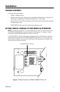
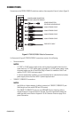
NOTE: TX Mode configuration must be set when the module is powered off. If you wish to change
a TX Mode switch setting after the module has been powered on, power off the module, change the
TX Mode switch setting, and then power on the module again.
MOUNTING
The FT82041/FR82041 module can be mounted into a rack or can be used as a stand-alone module.
As a stand-alone module, the unit can be placed on a desktop or can be mounted to a wall.
NOTE: As a matter of convenience, it is recommended that you set the modes of operation for each
10BASE-T/100-BASE-TX port—if required—before mounting the FT82041/FR82041 module into a
rack or onto a wall. For information about setting the port modes of operation, refer to Setting
10BASE-T/100BASE-TX Port Modes of Operation on page 11.
MOUNTING THE FT82041/FR82041 MODULE INTO A RACK
The FT82041/FR82041 module can be installed into an RK5000 Series rack mount chassis, which can
be mounted into an industry-standard 19-inch (48.26 cm) equipment rack. The RK5000 Series rack
mount chassis includes the following models:
• RK5000PS-3U and RK5000-3U: Designed to accommodate fiber optic modules as follows:
– The RK5000PS-3U rack mount chassis provides 12 single-width module slots and a
power supply.
– The RK5000-3U rack mount chassis provides 14 single-width module slots (a power
supply is not included). Power to the modules can be supplied using the optional
external power supply (EPS5000-120).
For additional information, refer to the RK5000PS-3U/RK5000-3U Fiber Rack Mount Chassis
Installation manual.
• RK5000PS-5U: Designed to accommodate Endura
™
modules but can also accommodate fiber
optic modules with the use of the appropriate adapter kit. The RK5001-1UEXP adapter kit is
required for installation of the FT82041/FR82041 module into the RK5000PS-5U chassis.
For information about the RK5000PS-5U chassis, refer to the RK5000PS-5U Rack Mount Chassis
Installation manual.
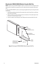
MOUNTING THE FT82041/FR82041 MODULE TO A WALL
The FT82041/FR82041 module can be mounted to a wall in the following ways:
• Using the supplied wall clip for attachment of a single module to a wall. For installation
instructions, refer to Mounting the FT82041/FR82041 Module Using the Wall Clip on page 14.
• Using the optional WM5001 wall mount kits, which are designed for mounting of single-width
fiber optic modules. The WM5001-3U base kit allows mounting of a single module to a wall.
The WM5001-3UEXP expansion kit allows mounting of an additional module. It is
recommended that a maximum of three expansion kits be used with the base kit, allowing a
maximum of four single-width modules to be mounted to a wall.
NOTE: The WM5001 wall mount kits can be used with the WM5002 wall mount kits, which are
designed for mounting of double-width fiber optic modules. If mounting a mix of single-width
and double-width modules is desired, it is recommended that a maximum of two single-width
modules and one double-width module be mounted in combination with one another.
For mounting instructions using the wall mount kits, refer to the WM5000 Series Wall Mount
Kit Installation manual.