


C2623M (2/07) 15
CONNECTIONS
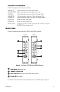
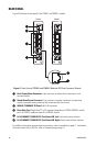
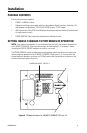
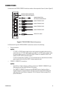
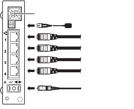
Connections to the FT82041/FR82041 module are made on the rear panel of the unit (refer to Figure 6).
Figure 6. FT82041/FR82041 Module Connections
As illustrated in Figure 6, FT82041/FR82041 connections consist of the following:
• Power connection
NOTES:
– A 12 VDC or 24 VAC power supply can be used to power the module when used as a
stand-alone unit. A 12 VDC power supply is provided. If a 24 VAC power supply is used,
the power supply must be a Listed Direct Plug-In Power Unit marked as Class 2 and
rated as 24 VAC, 0.50 A (minimum output).
– In extreme temperature conditions, it is recommended that an industrial-rated outdoor
power supply such as the Pelco WCS1-4 power supply be used.
• 10BASE-T/100BASE-TX connections
NOTES:
– Use Cat5e or a higher category of cable to connect to a 10BASE-T/100BASE-TX port.
Cable length must not exceed 328 feet (100 meters).
– The 10BASE-T/100BASE-TX ports are auto MDI/MDI-X ports; therefore, either a
straight-through or crossover cable can be used. The ports automatically detect the
cable type that is used. Refer to Appendix. RJ-45 Connector Pinouts on page 26 for
pinout information.
POWER CONNECTION
FOR STAND-ALONE MODULE
POWER/ALARM CONNECTION
FOR RACK-MOUNTED MODULE
10/100 NETWORK CABLE
10/100 NETWORK CABLE
10/100 NETWORK CABLE
10/100 NETWORK CABLE
FIBER OPTIC CABLE