


C2623M (2/07) 17
Troubleshooting
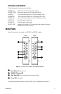
LED indicators on the front and rear panels of the FT82041/FR82041 module allow you to monitor
operational status:
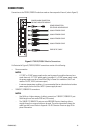
• LED indicators on the front panel allow you to monitor operating power, 100BASE-FX port
status, and optic signal/laser status. Refer to Table B for information about the front-panel
indicators and associated troubleshooting guidelines.
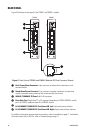
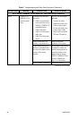
• LED indicators on the rear panel allow you to monitor RJ-45 10BASE-T/100BASE-TX port
status. Refer to Table C for information about the rear-panel indicators and associated
troubleshooting guidelines.
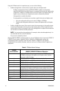
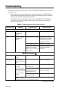
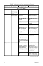
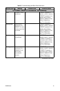
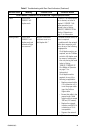
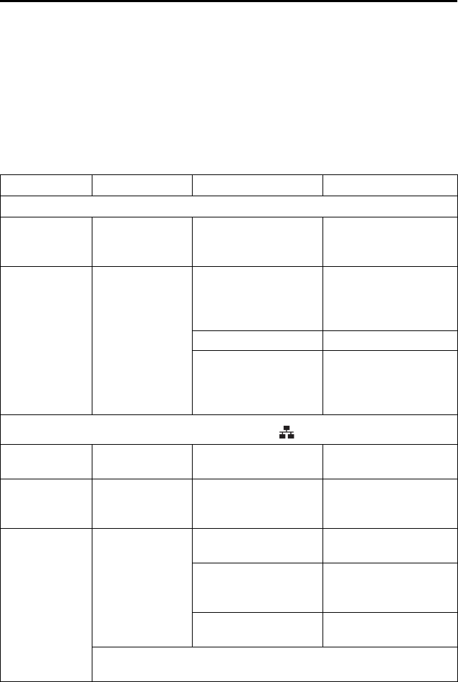
Table B. Troubleshooting with Front-Panel Indicators
Indicator Color Meaning Possible Cause Corrective Action
Power LED (Pelco badge)
Blue Power is being
applied to the
module.
– No action required.
Not lit Power is not being
applied to the
module.
Power connection is faulty. Check power connection.
If module is rack mounted,
reseat module or power
supply as necessary.
Power supply has failed. Replace power supply.
Loss of power occurs due to
tripped circuit breakers,
blown fuses, or faulty elec-
trical service.
Check circuit breakers, fuses,
or electrical service as
necessary.
100BASE-FX Status LED ( )
Green A fiber link is estab-
lished.
— No action is required.
Flashing green Data activity is
occurring on the fiber
link.
— No action is required.
Red Far end fault indica-
tion (FEFI).
The optical signal
transmitted from this
port is not detected
by the remote link
partner.
Defective fiber transmit port
on local module
Replace local module.
Laser fault on local module
(Optic Fault LED on local
module flashes red).
Refer to the Optic Fault LED
section in this table.
Defective fiber receive port
on remote module
Replace remote module.
NOTE: The Optic Fault LED on the remote module is red. Refer to the Optic Fault
LED section in this table for additional information.
(Continued on next page)