


14 C2604M (7/06)
MOUNTING
The FT85011A transmitter/FR85011A receiver can be mounted into a rack or can be used as a stand-
alone module. As a stand-alone module, the unit can be placed on a desktop or can be mounted to
a wall.
NOTE:
As a matter of convenience, it is recommended that you set the desired data communication
before
mounting the FT85011A transmitter/FR85011A receiver. To set the desired data
communication, refer to the
Data Communication Setup
section.
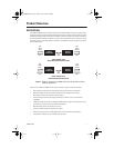
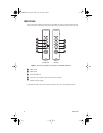
MOUNTING THE TRANSMITTER/RECEIVER INTO A RACK
The FT85011A transmitter/FR85011A receiver can be installed into an RK5000 Series rack mount
chassis, which can be mounted into an industry-standard 19-inch (48.26 cm) equipment rack.
The RK5000 Series rack mount chassis includes the following models:
•
RK5000PS-3U and RK5000-3U:
Designed to accommodate fiber optic modules as follows:
–
The RK5000PS-3U rack mount chassis provides 12 module slots and a power supply.
–
The RK5000-3U rack mount chassis provides 14 module slots (a power supply is not
included). Power to the modules can be supplied using the optional external power
supply (EPS5000-120).
For additional information, refer to the RK5000PS-3U/RK5000-3U Fiber Rack Mount Chassis
Installation manual.
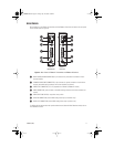
•
RK5000PS-5U:
Designed to accommodate Endura
™
modules but can also accommodate fiber
optic modules with the use of the appropriate adapter kit. The RK5001-1UEXP adapter kit is
required for installation of the FT85011A transmitter/FR85011A receiver into the
RK5000PS-5U chassis.
For information about the RK5000PS-5U chassis, refer to the RK5000PS-5U Rack Mount Chassis
Installation manual.
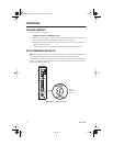
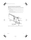
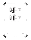
MOUNTING THE TRANSMITTER/RECEIVER TO A WALL
The FT85011A transmitter/FR85011A receiver can be mounted to a wall in the following ways:
•
Using the supplied wall clip for attachment of a single module to a wall. For installation
instructions, refer to the
Mounting the Transmitter/Receiver Using the Wall Clip
section.
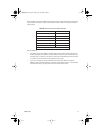
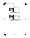
•
Using the optional WM5001 wall mount kits, which are designed for mounting of single-width
fiber optic modules. The WM5001-3U base kit allows mounting of a single module to a wall.
The WM5001-3UEXP expansion kit allows mounting of an additional module. It is
recommended that a maximum of three expansion kits be used with the base kit, allowing a
maximum of four single-width modules to be mounted to a wall.
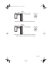
NOTE:
The WM5001 wall mount kits can be used with the WM5002 wall mount kits, which
are designed for mounting of double-width fiber optic modules. If mounting a mix of single-
width and double-width modules is desired, it is recommended that a maximum of two single-
width modules and one double-width module be mounted in combination with one another.
For mounting instructions using the wall mount kits, refer to the WM5000 Series Wall Mount
Kit Installation manual.
C2604M.book Page 14 Friday, July 14, 2006 1:08 PM