4 Pelco Manual C360M-I (11/99)
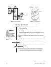
2. If you installed the scanner in an upright position, remove the 10-32 Allen screw from
the bottom plate. If you installed the scanner in an inverted position, remove the 10-32
Allen screw from the top plate. Retain the screw.
3. Center (balance) the camera and lens, or enclosure, camera, and lens load on the tilt
table. Adjust the positioning as needed to align the mounting holes. Mount the camera
or enclosure to the tilt table with two 1/4-20 hex head bolts (not supplied). Position the
camera at the desired angle by manually adjusting the tilt table.
ELECTRICAL INSTALLATION
This section provides instructions for wiring the scanner only. To wire the camera and lens
or camera enclosure, refer to the manuals for that equipment.
MATING CONNECTOR ASSEMBLY
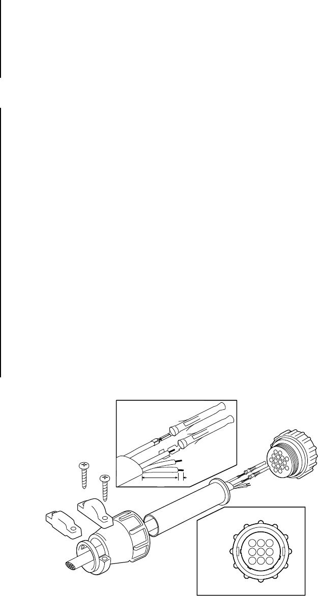
Assemble the cable to connect to the scanner. A mating connector is supplied as loose
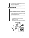
equipment. To assemble the mating connector, refer to Figure 1 and perform the following
steps.
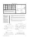
1. Refer to Figure 2 or 3 for the number of wires required. Choose between either con-
tinuous-duty or remote control operation. For remote control operation, refer to Table A
to determine the size of wire to use. Scanner distance can be extended with the use of
an RB115 (PS30A) or RB24 (PS30-24) Relay Box.
2. Slide the connector clamp assembly over the conductor cable. If the diameter of the
conductor cable is such that the rubber boot will slide over it easily, slide the rubber
boot onto the conductor cable at this time. If not, discard the rubber boot.
3. Refer to Detail A in Figure 1. Prepare the wires from the conductor cable as follows:
a. Strip at least one inch (2.54 cm) from the cable jacket to expose the wires. You
may need to strip more from the cable jacket if you have more wires.
b. Strip .125-inch (3 mm) from each wire.
c. Using an AMP style crimper, crimp the wires and their insulation to the connector
pins.
OR
1"
13
46
79
B FRONT VIEW
9 PIN
.125"
A
Figure 1. Connector Assembly


