Pelco Manual C360M-I (11/99) 5
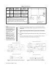
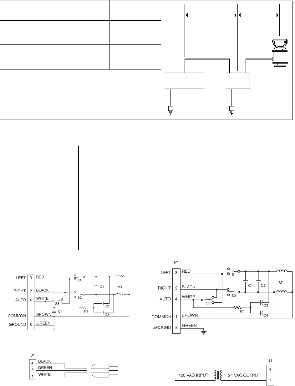
Model Wire Size Maximum Maximum
(AWG) Distance “A” Distance “B”
PS30A 20 5,800 ft (1,768 m) 2,467 ft (752 m)
18 8,250 ft (2,515 m) 3,925 ft (1,196 m)
16 13,000 ft (3,962 m) 6,229 ft (1,899 m)
PS30-24 20 5,800 ft (1,768 m) 118 ft (35 m)
18 8,250 ft (2,515 m) 188 ft (57 m)
16 13,000 ft (3,962 m) 298 ft (90 m)
NOTE:
If RB24 or RB115 Relay Box is not used, maximum cable
length is distance “B.”
* Conductors are for left and right functions, motor common, and
safety ground. Cable distances are calculated with the motor
running and assuming a 10% voltage drop in the cable.
** Not recommended for reliable service between control and relay
box.
**
**
A B
RB115
OR RB24
24 VAC
CONTROLLER
REQUIRES EXTERNAL
POWER SUPPLY
Table A. Cable Distances*
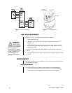
4. Slide the connector pins into the appropriate holes in the connector body until they
snap into place. Refer to detail B in Figure 1 and to Figures 2 and 3 for the correct pin
arrangement.
5. Push the connector clamp assembly (with boot, if used) toward the connector body.
Screw the clamp assembly onto the connector body, being careful not to disturb the
wires.
6. To complete the assembly, attach the appropriate clamp with the screws provided and
tighten.
7. For remote control operation, refer to Figure 4 to wire the other end of the cable. If a
relay box is not used, wire the scanner directly to the control unit.
NOTE:
Contacts cannot be
removed from the connector
without the use of the
appropriate AMP extraction
tool (ZT305183), which is
available from Pelco.
NOTE:
When a scanner is
mounted in the inverted
position, the LEFT/ RIGHT
functions are reversed
during operation. To correct
this problem, reverse the
LEFT/RIGHT functions in
the control cable (pins 3 and
2) at the scanner or control.
Figure 2. PS30A Schematic and Wiring Diagrams Figure 3. PS30-24 Schematic and Wiring Diagrams
REMOTE CONTROL OPERATION
CONTINUOUS-DUTY OPERATION
REMOTE CONTROL OPERATION
CONTINUOUS-DUTY OPERATION


