


Link Interfaces Reference
30
ATL-CSU/DSU Link Module Information
The ATL-CSU/DSU link module is normally configured to receive clock from the connected network.
When two ATL-CSU/DSU link modules are to be used on a leased line in a back-to-back set-up, one of the
modules must provide the clock.
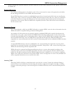
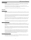
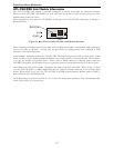
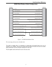
These modules may have either the UP/DOWN switch type or the ON/OFF slide switch type. Each type is
illustrated below.
Figure 3-1 Rear View of ATL-CSU/DSU Link Module Switches
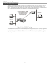
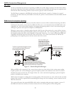
When connecting two bridge/routers back-to-back with CSU/DSU link modules, a null-modem cable is required to
crossover the pins on the links. Crossing over the pins allows two bridge/routers both configured as DTE
interfaces to be connected together.
Switch number 1 determines whether the
ATL-
CSU/DSU link module will generate clocks or receive clocks. When
switch 1 is down (on), the normal position, the module receive clocks from the connected network. When switch 1
is up (up), the module will generate clocks. When a pair of P2600 routers are connected back-to-back with
CSU/DSU link modules one module must be set to generate clocks and one module must be set to receive clocks.
On 64 Kbps units only, switch number 3 determines the mode of the
ATL-
CSU/DSU. When switch 3 is down
(on), the
ATL-
CSU/DSU is in DDS (Digital Data Service) mode for normal connection to the 64 Kbps digital
service. When switch 3 is up (off), the
ATL-
CSU/DSU is in LDM (Limited Distance Modem) mode for back-to-
back connection with a null-modem cable.
On 56 Kbps units, the position of switch 3 is not a factor for back-to-back connection with a null-modem cable.
Switch 1 must still be set as noted above.
CSU/DSU
LINE
1 2 3 4
Switches
up
down