


Link Interfaces Reference
36
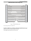
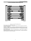
V.35 Link Pinouts
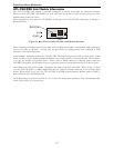
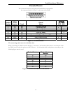
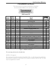
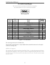
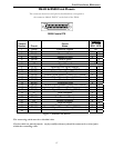
The connector pinouts described here correspond to the DB25 connector on the back of the P2600.
13
1
25
14
DB25 Female DTE
DB25
Contact
Number
M.34
Contact
Number
CCITT
Circuit
Number
Circuit
Name
Direction
To From
DCE DCE
1 A Protective Ground NA
2 ----------
3 ----------
4 C 105 Request to Send X
5 ----------
6 E 107 Data Set Ready X
7 B 102 Signal Ground NA
8 F 109 Data Channel Received Line Signal Detector X
9 P 103 Transmitted Data (A) X
10 S 103 Transmitted Data (B) X
11 R 104 Received Data (A) X
12 T 104 Received Data (B) X
13 ----------
14 V 115 Receiver Signal Element Timing (A) X
15 ----------
16 X 115 Receiver Signal Element Timing (B) X
17 ----------
18 U 113 Transmitter Signal Element Timing (A) DTE X
19 W 113 Transmitter Signal Element Timing (B) DTE X
20 H 108.2 Data Terminal Ready X
21 141 Local Loopback X
22 J 125 Calling Indicator X
23 Y 114 Transmitter Signal Element Timing (A) X
24 ----------
25 a 114 Transmitter Signal Element Timing (B) X
Figure 3 – 9 V.35 Link Pin Outs
The connecting cable must be a shielded cable.
Circuits which are paired (contain an (A) and (B) reference) should be connected to twisted pairs
within the connecting cable.
NOTE For U.K. Approval:
The connecting cable should be manufactured from Belden Cable, or a cable with equivalent specifications.
One end must be terminated in a male 34 pin X.21 bis connector as defined in ISO-2593 1984. The other
end must be terminated in a male 25 pin X.21 bis connector as defined in ISO-2110 1989. The cable may be
any length between 0 and 5M.