


F. Connection Instructions
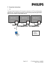
1. VGA
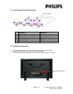
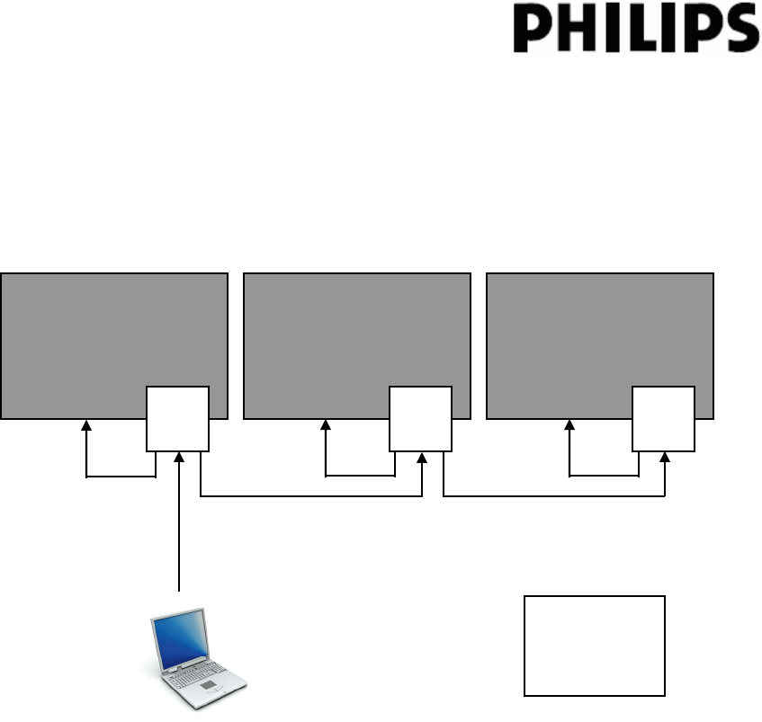
The diagram below illustrates the VGA connection configuration to a PC and multiple displays.
Important note: The VGA cable from the PC to the first display should be type E101344
with all 15 pins available to ensure EDID read out.
BDLX231
3
BDLX231
3 3
2
1
*DB15
M
-
M
VGA In
CRA01
BDLX231
2
1
*DB15
M
-
M
VGA In
CRA01
1
2
VGA In
CRA01
*DB15
M
-
M
DB15 M-M
DB15 M-M
DB15
M-M
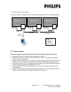
Legend:
1 – VGA Local
2 – VGA In
3 – VGA Out
* cable provided
Page 6 of 9 LT Installation Guide 1.1 (140907)
12NC: 3139 125 39281