


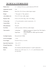
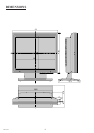
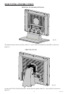
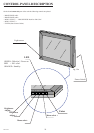
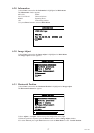

13
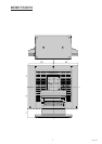
MCL1801
AC INLET
MAINS SOCKET
RS232
or
TOUCHSCREEN
DVI-INPUT
VIDEO-INPUT
XVGA
INPUT INSTRUCTION
fi g.13a
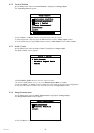
AC INLET (Meet IEC 320/CEE 22 STANDARD)
110/220Vdc
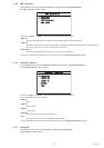
RS232 / TOUCHSCREEN Connector (RJ11-4)
Pin 1 : RS232 Rx
Pin 2 : RS232 Tx
Pin 3 : ENABLE (Only with touch screen)
Pin 4 : GND
Note: When the option touchscreen is used, the RS232 monitor control is not available.
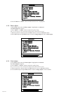
DVI INPUT Connector (Microcross™ DVI-D female connector)
Pin 1 : D2_RX - (T.M.D.S.) Pin 13 : N.C.
Pin 2 : D2_RX + (T.M.D.S.) Pin 14 : +5V Power
Pin 3 : GND (Data 2 shield) Pin 15 : GND
Pin 4 : N.C. Pin 16 : Hot Plug Detect
Pin 5 : N.C. Pin 17 : D0_RX - (T.M.D.S.)
Pin 6 : SCL (For DDC) Pin 18 : D0_RX + (T.M.D.S.)
Pin 7 : SDA (For DDC) Pin 19 : GND (Data 0 shield)
Pin 8 : N.C. Pin 20 : N.C.
Pin 9 : D1_RX - (T.M.D.S.) Pin 21 : N.C.
Pin 10 : D1_RX + (T.M.D.S.) Pin 22 : GND (Clock shield)
Pin 11 : GND (Data 1 shield) Pin 23 : CK_RX + (T.M.D.S.)
Pin 12 : N.C. Pin 24 : CK_RX - (T.M.D.S.)
VIDEO INPUT XVGA Connection (DSUB15 female connector)
Pin 1 : R-in Pin 9 : N.C.
Pin 2 : G-in Pin 10 : GND
Pin 3 : B-in Pin 11 : N.C.
Pin 4 : N.C. Pin 12 : SDA (For DDC option)
Pin 5 : N.C. Pin 13 : H.S.-in
Pin 6 : GND Pin 14 : V.S.-in
Pin 7 : GND Pin 15 : SCL (For DDC option)
Pin 8 : GND