Philips Semiconductors
UM10014_4
ISP1520 Hi-Speed USB Hub Demo Board
© Koninklijke Philips Electronics N.V. 2004. All rights reserved.
User manual Rev. 04.00 — 11 May 2004 8 of 18
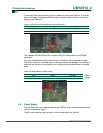
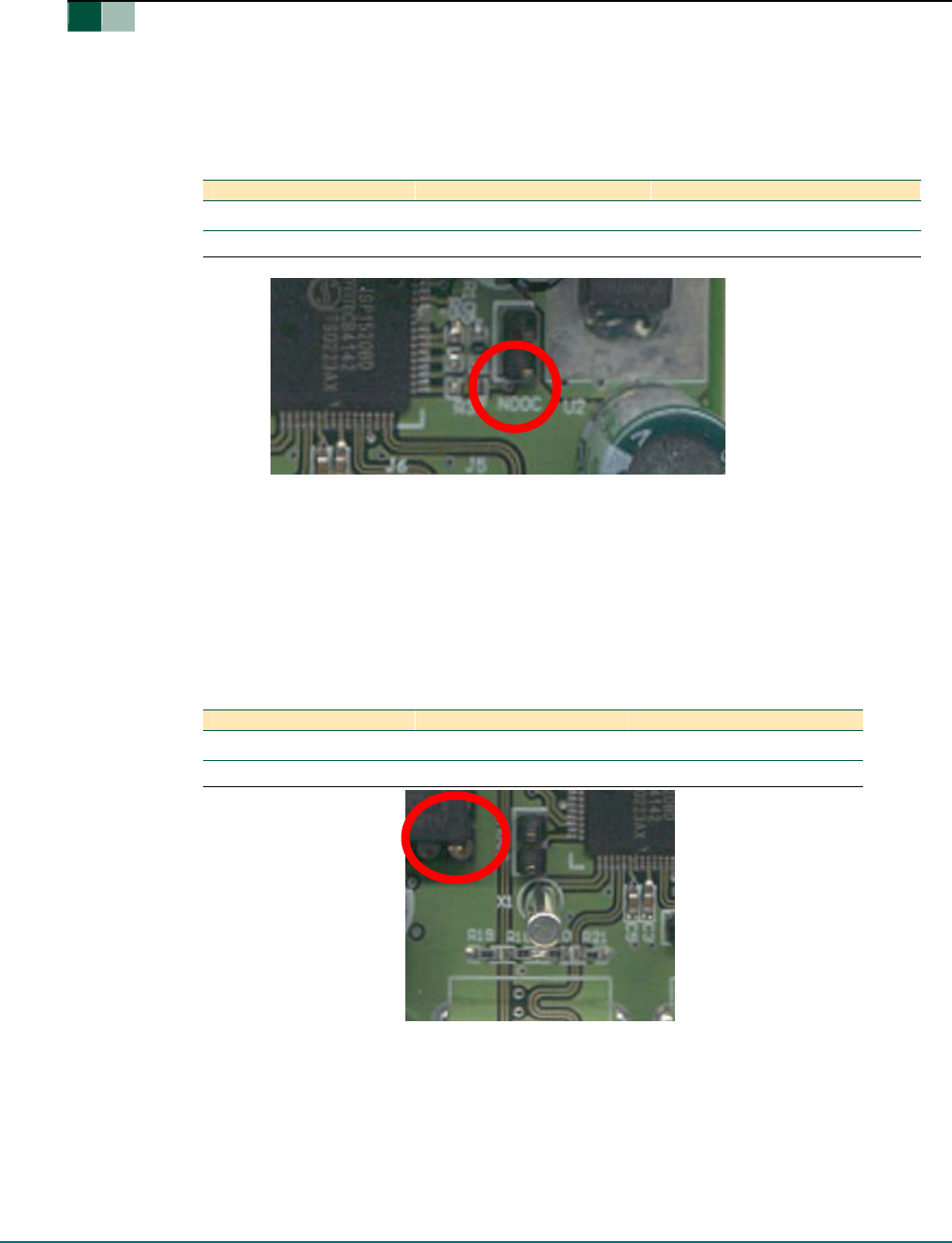
The hub demo board also contains an option to disable the overcurrent detection. This can be
done in two stages. First place the NOOC jumper in the appropriate position to set the hub’s
descriptor (see Table 5-2).
Table 5-2: Overcurrent Detection Selection Using NOOC
Then, desolder R28, R29, R30 and R31, and solder R32, R33, R34 and R36 on the PCB (see
schematics).
As a lower cost alternative, there are provisions on the board to use polyswitches to handle
overcurrent conditions. In this case the port switching transistors are bypassed. If this solution is
preferred, then the overcurrent detection circuit inside the chip must be switched to the digital
mode
Table 5-3: Mode Selection Using ADOC
*—
Default
settings.
5.5. Power Supply
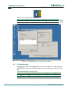
This hub demo board can be used as a self-powered USB hub. When used as a self-powered hub,
use the provided power supply.
The SW1 switch sets the powering mode in the hub’s descriptors; see Table 5-4.
NOOC Overcurrent Detection Logic State
ON YES 0 (LOW)
OFF NO 1 (HIGH)
ADOC Mode Logic State
ON Digital 0 (LOW)
OFF Analog* 1 (HIGH)


