


6
2.3 UPS overview
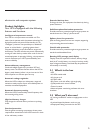
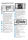
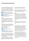
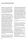
Front panel
Power switch: Turns power to the UPS
on or off. May be used as the master
ON/OFF switch for all equipment
connected to the battery back-up out-
lets by leaving the power buttons for
the connected equipment ON. Also
indicates the status of the UPS:
• a steady light indicates the UPS is in-
line mode and using AC current
• a flashing light indicates the UPS is in
battery back-up mode
Time set control (minutes): Use this
button to set the time in minutes.
Liquid crystal display (LCD) message
panel: Displays UPS status information
and time.
Surge protection LED indicator: A
steady light signals surge protection
is normal.
Ground LED indicator: A steady light
signals grounding is normal.
EMI/RFI LED indicator: A steady light
signals noise filtration is functioning
properly.
Time set control (hours): Use this but-
ton to set the time in hours.
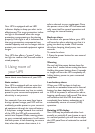
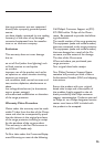
LCD message panel display
Digital clock: Displays present time.
AVR (Automatic Voltage Regulation)
indicator: Illuminated “AVR Activate”
signals the AVR is actively functioning.
Battery charge level: Signals the bat-
tery charging level in AC mode.
Battery run time: Signals battery status
in back-up mode.
Input voltage: Measures the input
voltage.
Battery load level: Signals the total
output load of the UPS.
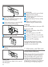
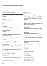
Back panel
Network line protection
Telephone line protection with splitter
(1 in/2 out)
USB port for software/computer
interface
Surge protected outlets, stage
1 (up to 40dB)
Surge protection outlets, stage
2 (up to 58dB)
UPS battery back-up outlets, stage 3
(up to 65dB)
Circuit breaker
Power cord input
Four sets of coaxial line protection
-
with gold connectors
1 2 3 4
6
5
7
1
2
3
4
5
6
7
1
2
3
4
5
6
1
5
6
2
3
4
1
2
3
4
5
6
7
8
9
541 6
9
7
8
2 3