


PN: 1725-36031-001_H.doc
19
Installing the SpectraLink 8000
SVP Server
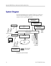
As shown in the system diagram, the SVP Server is connected to the
Ethernet switch. The specifications covered here allow for great
flexibility in physical placement of the components within stated
guidelines.
See the Configuration and Administration document for your vendor’s
IP system for information on LAN requirements, network
infrastructure and IP addressing.
This unit must be installed by a service person familiar with the
installation of electronic equipment.
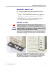
Do not power up the unit before it has been properly grounded to a
protective earth. See Grounding Instructions below.
Required Materials
The following equipment must be provided by the customer.
Power Outlet – AC adapter provided by Polycom.
Backboard space – the SVP Server is designed to be wall- mounted
to 3/4" plywood securely screwed to the wall.
Screws – required to mount the SVP Server to the wall. Four #8
3/4" panhead wood screws (or similar device) are required.
Cat. 5 Cable – RJ-45 connector at the SVP Server. Connection to
Ethernet switch.
Grounding materials per section below Grounding Instructions.
2