Integrators’ Reference Manual for ViewStation EX, ViewStation FX, and VS4000
38 www.polycom.com
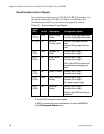
Serial Interface Control Signals
If you need to customize your V.35/RS-449/RS-530 interface, use
the signal information in Table 2-21 below in addition to the
information provided by your network equipment vendor.
Table 2-21. Serial Interface Control Signals
Signal
(Pin) In/Out Description Configuration Option
ST
(TC/TT)
OUT Send Timing
(clock)
Normal: falling edge sends data
Inverted: rising edge sends data
RT (RC) IN Receive
Timing (clock)
Normal: rising edge receives
data
Inverted: falling edge receives
data
RTS
(RTS)
OUT Request To
Send
Normal: high is logic 1
Inverted: low is logic 1
DCD
(DCD)
IN Data Carrier
Detect
Normal: high is logic 1
Inverted: low is logic 1
Filter: allow DCD to drop for 60
seconds before changing call
state
CTS
(CTS)
IN Clear To Send Normal: high is logic 1
Inverted: low is logic 1
DTR
(DTR)
OUT Data Terminal
Ready
Normal: high is logic 1
Inverted: low is logic 1
On: signal remains high
a
a. If set to ON, inverted is not an option.
DSR
(DSR)
IN Data Set
Ready
Normal: high is logic 1
Inverted: low is logic 1
Answer: Use DSR as a Ring-In
indication
b
b. DSR is not used as a ring-in indication if it is set to ANSWER in
the V.35 Advanced Setup screen.


