


Installation
30
Powerware
®
9150 User’s Guide www.powerware.com
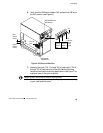
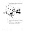
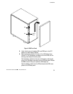
10. Connect the wire cover to the PDM using the two screws
provided (see Figure 10).
11. Reinstall the UPS left side panel. (Do not reinstall the front
panel at this time.)
12. Lower the leveling feet to prevent the UPS from rolling (does
not apply for seismic mounting installations).
13. If you have additional battery cabinets, continue to the
following “External Battery Cabinet Installation” procedure.
Otherwise, skip to “UPS Startup” on page 33.
External Battery Cabinet Installation
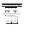
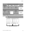
The Powerware 9150 UPS has either 32 or 48 internal batteries. EBCs
are available for the 48-battery model. Refer to the UPS serial nameplate;
the DC voltage on the nameplate must be 288V to add EBCs.
The internal battery charger can support additional EBCs; however,
additional battery capacity also extends the recharge time.
NOTE A service representative must change the Battery Size parameter in the
nonvolatile memory to reflect the correct number of battery strings after installing
EBCs.
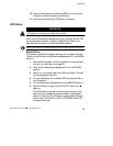
WARNING
Only qualified service personnel (such as a licensed electrician) should perform the
UPS installation and initial startup. Risk of electrical shock.
Use the following instructions for installing an EBC with the 48-battery
UPS:
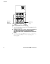
1. If the UPS is operating, turn the Maintenance Bypass switch to
the BYPASS position and turn off the UPS ON/OFF switch (the
position). See Figure 6 on page 23.
2. Verify the circuit breakers on the UPS are in the OFF position.
3. Facing the UPS, place the battery cabinet to the right of the
UPS. Confirm the DC voltage on the nameplate of the UPS and
EBC is 288V.
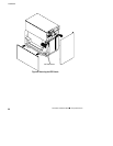
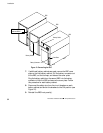
4. Remove the front panel of each EBC. Lift from the bottom of
the panel and then pull out (see Figure 12).