


Operation
49
Powerware
®
9150 User’s Guide www.powerware.com
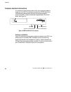
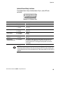
Isolated Alarm Relay Interface
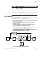
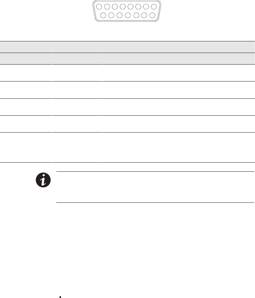
The isolated alarm relay interface uses a 15-pin, male, 42D-sub
connector.
12345678
9101112131415
Figure 21. 15-Pin Serial Port
Relay Interface of Powerware 9150
Pin No. Connection System State
Utility Failure 1-2Closed
1-3Closed
Line normal
Line failure
Low Battery 4-5Closed
4-6Closed
Battery normal
Battery low
UPS on Bypass 10- 11 Closed
10 - 12 Closed
On UPS
On Bypass
UPS On or
UPS Alarm
7-9Closed
7-8Closed
UPS on
UPS alarm
UPS Shutdown
(in Battery Mode only)
13 - 15 Closed UPS shutdown when operating in Battery Mode. UPS can be shut down
by sending a hi-level signal (+5V to +15V) to Pin 15(+) and 14(-), or by
connecting Pin 15 to Pin 13. This signal must be present for a minimum
of 5 seconds.
NOTE The relay contacts are rated for a maximum 1A/30 Vac or 0.2A/60 Vdc. All
relay outputs are isolated from the other circuits of the UPS. The relay contacts must
not be connected to any utility connected circuits. Reinforced insulation to the utility is
required.