


Communication
71
Powerware
®
9170 User's Guide S LTM-1344 B Uncontrolled Copy
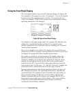
Dedicated Input Signals
Emergency Power-Off (EPO): Connection to a facility Emergency Shutdown
switch provides a method for emergency Powerware 9170 system
shutdown. Opening this connection creates an immediate shutdown of
the Powerware 9170 UPS output.
Bypass: The signal from an external bypass switch, to isolate the
Powerware 9170 system for maintenance purposes, tells the UPS to go
into Internal Bypass mode.
On-Generator: An external signal that the input power is being supplied
by a generator tells the UPS to accept wider input power frequency
limits.
See Figure 21 on page 31 and Figure 24 on page 34 to make the
connection for all dedicated input signals.
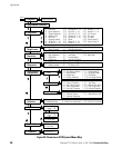
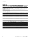
DB-9 Port Pin Functions
Table 10 explains the functions of the pins on the Powerware 9170 DB-9
port. This port is on the Powerware 9170 UPS rear panel, as shown in
Figure 42 on page 52.
Table 10. DB-9 Port Signals
Pin Function Description
1 RS-232 Receive Data Receives incoming RS-232 communication data. The data protocol is 9600 baud, 8 bits,
no parity, 1 stop bit, no handshaking.
NOTE In battery operation, a 5-second +Vdc (RS-232 low) signal applied to this pin
causes the UPS to shut down after a delay of X minutes, regardless of the return of AC
input power. This time is defined by the External Shutdown mode parameter n, where n
and X are related as follows:
nX nX nX
02 33 620
1* 2 4 5
21 510
* For n=1, the UPS stays off when AC input power returns. For all other values of n, the
UPS restarts 12 seconds after AC input power returns.
2 RS-232 Transmit Data Sends outgoing RS-232 communication data. The data protocol is 9600 baud, 8 bits, no
parity, 1 stop bit, no handshaking.
3 Normally-Open
On-Battery Contact*
A normally open contact that closes (pulls to Common) 15 seconds after the UPS
switches to battery power.
4 Common The ground reference for all input and output signals.