


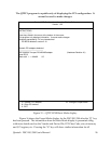
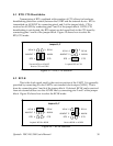
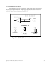
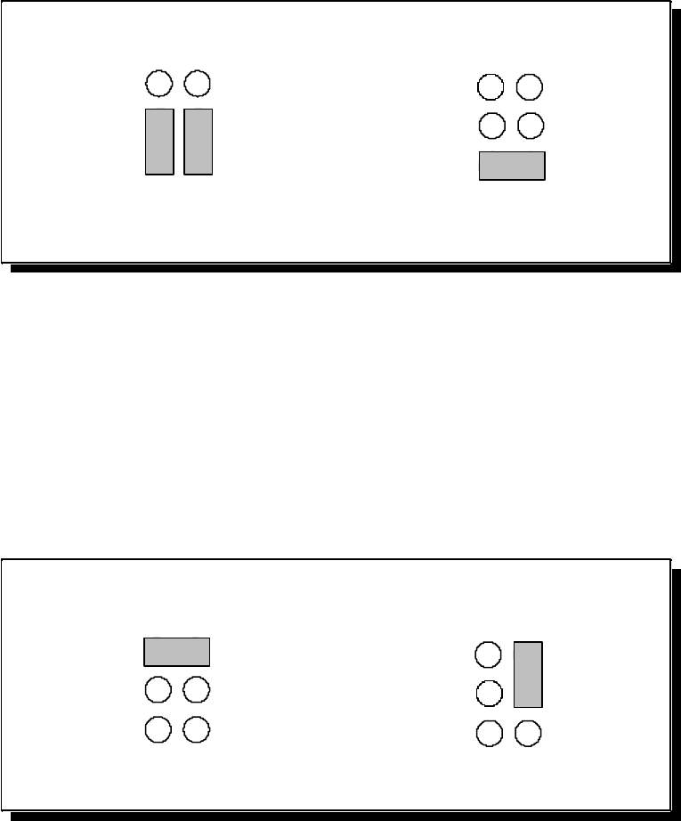
8.1 RTS/CTS Handshake
Transmission of RTS, combined with reception of CTS, allows for hardware
handshaking (data flow control) between the UART and the external device. RTS is
transmitted on AUXOUT by connecting pins 4 and 5 of the jumper block. CTS is
received on AUXIN by connecting pins 1 and 2 of the jumper block. If RTS/CTS
handshaking is not desired, the RTS output can be looped back to the CTS input by
connecting pins 1 and 4 of the jumper block. Figure 19 shows how to select the
RTS/CTS mode.
Transmit RTS on AUXOUT
Receive CTS on AUXIN
Loopback RTS to CTS
CTS
AUXIN
XCLK
RTS
AUXOUT
RCLK
1
2
3
6
5
4
CTS
AUXIN
XCLK
RTS
AUXOUT
RCLK
1
2
3
6
5
4
Jumpers J5, J7
Figure 19 --- RTS/CTS selection
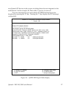
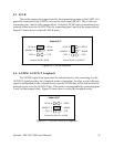
8.2 RCLK
This is the clock signal used by the receiver portion of the UART. It is generally
provided by connecting it to the UART's own transmit clock output (XCLK). This is
done by connecting pins 3 and 6 of the jumper block. If desired, RCLK can be received
from an external source over the AUXIN line by connecting pins 2 and 3 of the jumper
block. Figure 20 shows how to select the RCLK mode.
Loopback XCLK to RCLK Receive RCLK on AUXIN
CTS
AUXIN
XCLK
RTS
AUXOUT
RCLK
1
2
3
6
5
4
CTS
AUXIN
XCLK
RTS
AUXOUT
RCLK
1
2
36
5
4
Jumpers J5, J7
Figure 20 --- RCLK selection
Quatech DSC
-200/300 User
'
s Manual
30