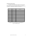
MODEM STATUS REGISTER
This register is located at I/O address [base+6]. It reports on the status of
signals coming from the modem or equipment used in place of a modem. It
allows the current states of "modem control signals" to be sensed. These signals
include the DCD (Data Carrier Detect), RI (Ring Indicator), DSR (Data Set
Ready), and CTS (Clear To Send).
The Modem Status Register also provides change information for each of
these signals. When a modem control signal changes state, the appropriate change
bit is set to logic 1. The change bits (3, 2, 1, and 0) are reset to logic 0 whenever
the Modem Status Register is read.
A modem status interrupt is generated whenever any of bits 3, 2, 1 or 0 is
set by the UART to a logic 1.
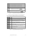
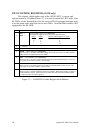
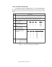
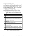
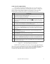
DCTS --- Delta clear to send:
Indicates the Clear to Send input has changed state.
Cleared when this register is read.
0
DDSR --- Delta data set ready:
Indicates the Data Set Ready input has changed state.
Cleared when this register is read.
1
TERI --- Trailing edge ring indicator:
Indicates the Ring Indicator input has changed from a low to a high state.
Cleared when this register is read.
2
DDCD --- Delta data carrier detect:
Indicates the Data Carrier Detect input has changed state.
Cleared when this register is read.
3
CTS --- Clear to send:
Complement of the CTS input.
4
DSR --- Data set ready:
Complement of the DSR input.
5
RI --- Ring indicator:
Complement of the RI input.
6
DCD --- Data carrier detect:
Complement of the DCD input.
7
DESCRIPTIONBIT
Figure 21 --- Modem Status Register bit definitions
SCRATCHPAD REGISTER
This register is located at I/O address [base+7]. It is not used by the 16450
or 16550. It may be used by the programmer for temporary data storage. The
Scratchpad Register is eight bits wide and can be read or written.
20
Quatech ES-100D User's Manual


