


2.2 Signal Connections
The DSCLP-200/300 provides each of two serial ports with four
differential signal pairs: TxD, RxD, AUXOUT, and AUXIN. TxD and RxD are
always present at the connector. The AUXOUT and AUXIN signals can be used
to support RTS/CTS handshaking, external clocking, or external signal loopback.
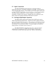
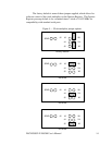
The factory default configuration, as shown in Figure 2, is a loopback of
AUXOUT to AUXIN at the connector, with RTS and CTS looped back on the
board. There is an extensive discussion of this topic in section 7.
2.3 Full-duplex/Half-duplex Operation
The DTR or RTS modem control output of the UART can be used to
enable and disable the transmit drivers. The inverse of these signals can also be
used to enable and disable the receivers. These options are selectable per channel.
The factory default, as shown in Figure 2, is for both the drivers and receivers of
both channels to be continuously enabled. Two spare jumpers are installed in
neutral positions. For details, refer to section 7.5.
The DSCLP-200/300 is shipped from the factory with each channel
configured with No jumpers on J10-23. The following conditions occur:
CTS=AUXIN, AUXOUT=RTS, RCLK=TCLK, TXEN=1 AND RXEN=1.
DSCLP/SSCLP-200/300 User's Manual 10