


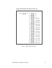
2.4 Clock Rate and Optional Registers
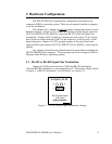
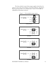
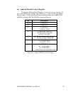
Figure 3 shows the jumper configuration as shipped from the factory, with
two spare jumpers applied in neutral positions. Remove one or both and apply as
shown in following subsections to set optional features.
X8
X4
X2
J3
J4
J5
J2
SPAD
Figure 3 --- Factory default clock rate and options settings
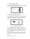
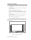
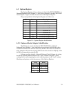
2.4.1 Enable Scratchpad Register (SPAD, J2)
In the default configuration (see page 11), an Interrupt Status Register and
an Options Register replace the scratchpad (base address + 7) of each UART. If
the SPAD jumper is applied as in Figure 4, the UART scratchpad registers are
enabled, and the Interrupt Status Register and the Options Register are not
available.
X8
X4
X2
J3
J4
J5
J2
SPAD
Figure 4 --- Enable scratchpad registers
2.4.2 Force High-Speed UART Clock (X2, X4, or X8; J3, 4, 5)
These jumpers force an increase of the UART input clock frequency by a
factor of two, four, or eight. This feature can allow legacy software to use baud
rates above 115,200 bits per second. It is also useful if the serial port device
driver does not directly support setting the higher baud rates through the Options
Register (see section 4.5).
If one of these jumpers is applied, it overrides any value written to the
Options Register to set the clock multiplier by software. The effective baud rate
will be either two, four, or eight times the value for which the UART itself is
programmed.
DSCLP/SSCLP-200/300 User's Manual 13