


3 Hardware Installation
1. Turn off the power of the computer system in which the DSCLP-200/300
is to be installed.
2. Remove the system cover according to the instructions provided by the
computer manufacturer.
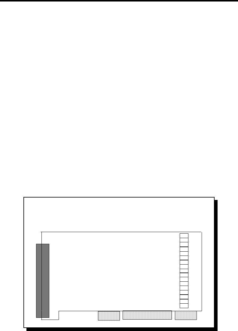
3. Make any desired optional jumper setting changes.
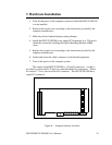
4. Install the DSCLP-200/300 in any empty PCI expansion slot. The board
should be secured by installing the Option Retaining Bracket (ORB)
screw.
5. Replace the system cover according to the instructions provided by the
computer manufacturer.
6. Attach and secure the cable connectors to the desired equipment.
7. Turn on the power of the computer system.
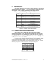
The output of the DSCLP-200/300 is a 25-pin D-connector. A cable is
provided to convert the D-25 into two standard female D-9 connectors. Please
see section 7.7 for a pin-out of the D-9 connector. The SSCLP-200/300 has a
single D-9 connector.
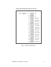
Figure 6 --- Jumper/connector locations
DSCLP/SSCLP-200/300 User's Manual 15