


890-007 Rev. A 01/28/99 Page 3 © 1999 RadioLAN, Inc.
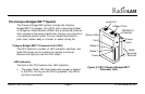
The Campus BridgeLINK™ System
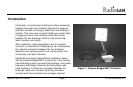
The Campus BridgeLINK system includes the Campus
BridgeLINK™ Processor Unit (CPU) with a mounting bracket,
a Companion Radio Module (CRM), and a directional antenna.
Also included is the power transformer that you can plug into a
non-switched electric outlet. You can install these items in
plain view, hidden away in a closet, or above ceiling tile.
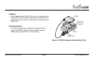
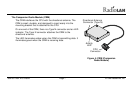
Campus BridgeLINK™ Processor Unit (CPU)
The CPU features a number of LED indicators, switches, and
jacks that allows you to connect the module to external
devices and help you see the CPU status.
LED Indicators
The face of the CPU features four LED indicators:
• The green Power LED illuminates when power is applied
to the CPU. As long as the CPU is powered, this LED is
normally illuminated.
Local Port
10BaseT Port
MDI/MDI-X
Selector
Power
Status 1
Status 2
Fault
Status LEDs:
Power
Jack
Radio
Mounting
Bracket
Figure 2: CPU (Campus BridgeLINK™
Processor Unit)