


ii FIGURES
Figures
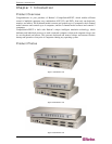
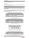
Figure 1 CS-PENT 2 Unit............................................................................................................................. 1
Figure 2 CS-PENT 4 Unit............................................................................................................................. 1
Figure 3 CS-PENT 8 Unit............................................................................................................................. 1
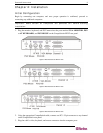
Figure 4 Rear Panel of CS-PENT 2 Unit......................................................................................................3
Figure 5 Rear Panel of CS-PENT 4 Unit......................................................................................................3
Figure 6 Rear Panel of CS-PENT 8 Unit......................................................................................................3
Figure 7 Cabling Details...............................................................................................................................4
Figure 8 Front panel of CS-PENT 2 Unit...................................................................................................... 5
Figure 9 Front Panel of CS-PENT 4 Unit ..................................................................................................... 5
Figure 10 Exploded View of Scan Rates from the CS-PENT 4 Front Panel ................................................ 5
Figure 11 Front Panel of CS-PENT 8 Unit ................................................................................................... 5
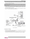
Figure 12. RCS24 to CS-PENT 2/CS-PENT 4 Installation......................................................................... 11
Figure 13. RCS8 to CS-PENT 8 Installation............................................................................................... 12