


18 Radome Scanners - Users Guide
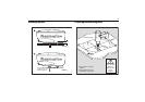
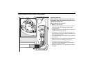
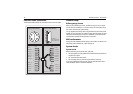
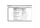
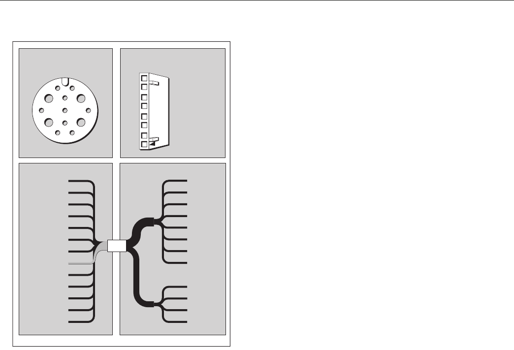
Inter-unit cable connections
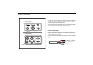
The illustration below details the connections for the inter-unit cable:
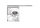
Scanner setup
Before you go to sea
After you have installed your radar, and before you go to sea, it is impor-
tant to check the installation. You can then set up the radar system, align
the scanner and check the system timing.
Set up, alignment and timing checks are performed from the radar system
display unit. The procedures are outlined on this page; full details are avail-
able in the relevant display unit Owner’s Handbook. You should read this
and familiarize yourself with the operation of the radar.
EMC conformance
Always check the installation before going to sea to make sure that it is not
affected by radio transmissions, engine starting, etc.
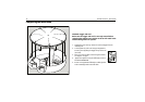
System checks
System check
Before performing any functional tests, make sure:
• All securing bolts are fully tightened and mechanical locking devices as
specified are in place.
• All connections have been made.
• All connecting wires are secured and protected as necessary.
If you have installed the radar yourself, ask your local Raymarine autho-
rized installation dealer to check the installation.
1
2
35
4
7
10
11
86
9
13 12
Black
White
Orange
Black
Black
Green
Yellow
Shield
Red
Red
Violet
Blue
Grey
Video
Video RTN
*Battery --ve
Tx Trigger +
Battery --ve
Data I/O +
Tx Trigger --
Battery +ve
Data I/O --
*Battery +ve
Azimuth +
Azimuth --
1
2
3
4
5
6
7
8
9
10
11
12
13
White
Black
Orange
Yellow
Green
Blue
Violet
Grey
Red
Red
Black
Black
8
7
6
5
4
3
2
1
Video
Video Rtn
Tx Trigger +
Tx Trigger --
Data I/O +
Data I/O --
Azimuth +
Azimuth --
Battery +ve
*Battery +ve
*Battery --ve
Battery --ve
Not fitted on
Open Array Scanners
(refer to Section 2.2)
Front view of
Display Cable Connector
Front view of Radome
Scanner Cable Connector
Display Scanner
* Not present on 'light', 11 core cables.
Battery +ve/--ve = 12 or 24v.
D8866_1
2
1
4
3
6
5
8
7