


- -8
4 OPERATING NOTES
The RMB-167 needs two connections: to a 5 volt well regulated power supply and to the serial
port of a host via a modem cable.
4.1 Power
Power is brought to the RMB-167 board by a two-position screw-type terminal block. A well
regulated 5 volt DC source is required. The (+) and (-) terminals are marked on the board. Note
that a diode is placed across the input in reverse. Thus if the power is applied to the RMB-167
board in reverse polarity, the diode will short the power supply attempting to prevent damage to
the board. Populated with 64K of CMOS RAM, the RMB-167 draws less than 175 mA.
4.2 Serial port 0
Serial port 0 is accessed through the RS-232 level converter U11. The microcontroller supports
the transmit and receive signals. A minimal serial port may be constructed with just 3 lines:
transmit, receive, and ground, disregarding all hardware handshake signals. Port P1 (HOST) of
the RMB-167 is a DB-9 female connector used to connect the board to an IBM compatible PC. A
straight-through modem cable may be used. That is a cable connecting pin 2 of the RMB-167 to
pin 2 of the host, and similarly pin 3 to pin 3, and pin 5 to pin 5. This cable and a DB9-DB25
adapter is supplied when the board is purchased directly from Rigel Corporation. JP11 is a 3-pin
header, which carries the same signals as P1. It is convenient if the board is to be used as an
embedded controller. JP11 is also denoted by S0, and its 3 lines by G (Ground), T (Transmit),
and R (Receive) on the RMB-167 silk-screen.
4.3 Serial Port 1
Serial port 1 is used as a synchronous serial channel by the SAB-C167. It has 3 TTL-level
signals, MRST (Master Receive Slave Transmit). MTRS (Master Transmit Slave Receive), and
SCLK (Serial Clock). Header JP12 carries these three signals as well as provides VCC and GND
for reference. Header JP12 is also denoted by SSC (Serial Synchronous Channel) on the silk-
screen. The individual pins of the header are denoted by VCC, R, T, C, and GND, which
correspond to VCC, MRST, MTSR, SCLK, and GND, respectively.
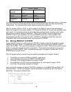
4.4 Jumper Selection
Two jumpers are needed to use the RMB-167 in the default 64K/256K RAM and no EPROM
mode. These should be placed at the Options jumper JP3 corresponding to P0.4 and P0.6. The
jumper at P0.4 invokes the bootstrap mode upon a reset. P0.6 selects the bus configuration.
4.5 LEDs
The RMB-167 has three LEDs. The red LED, when lit, shows power is connected to the board.
The yellow LED is an auxiliary LED, whose state is determined by the GAL equations. For
example the user may program the yellow LED to indicate the presence of a program in EPROM.
The default PAL equations set the yellow LED to be the complement of the green LED.
The green LED indicator marked RO (Reset Out) is connected to a GAL device. The LED is
turned on after system initialization is completed. More specifically, the LED is turned on when
the RSTIN# is high and RSTOUT# makes a 0-to-1 transition, which normally follows an EINIT
instruction.
The LED RO will be off and remain off until the bootstrap loader successfully completes loading
the bootstrap file into RAM.