


- -22
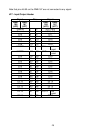
Note that the NOP (no operation) operations are required to fill the 32 bytes, since the bootstrap
loader remains active until all 32 bytes are received. When the bootstrap loader receives its last
byte and places it in address 0FA5Fh, it makes a jump to 0FA40h and starts executing the code.
This is the short loop given above. Note that at this time the internal RAM starting from 0FA60h
does not contain any relevant code.
The short loop takes advantage of the serial port S0 which is already initialized. It waits for a user
specified number of bytes, 604 bytes in this case, and places these bytes consecutively starting
from internal RAM location 0FA60h. When the loop is done (all 604 bytes received) the program
continues by executing the NOP operations, and then executing code from 0FA60h on. Thus the
604 bytes loaded by the secondary loop are also interpreted as code.
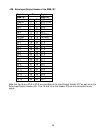
The user may alter the number of bytes to be loaded by changing the 21st and 22nd bytes (BB
and FC) which give the address (the low byte, followed by the high byte) of the last byte to be
read by the loop. Note that there is a practical limit to the number of bytes that can be
downloaded by this loop: the PEC source and destination pointers as well as the SFRs which
occupy addresses FDE0h and above must not be overwritten by data bytes.
Due to the powerful instruction set of the C167, a lot of functionality can be implemented within
604 bytes of code. The 604 bytes contained in the file BTL67.DAT downloads a minimal monitor
program. This program contains an initialization routine, subroutines to send and receive
characters through the serial port, a subroutine to download code in the Intel Hex format, and a
subroutine to jump to any location within the 64K segment. The latter two are invoked by single-
letter commands.
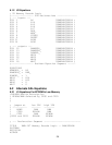
The 604 byte-code may be broken down into four sections.
1. Initialization code to be executed after the 32-byte bootstrap
2. Code to be written starting at address 0 to be executed after the software reset.
3. The minimal monitor to be placed starting at address 8000h
4. The software reset (SRST) instruction to leave the bootstrap mode.
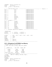
Sections 1 and 4 are somewhat different than sections 2 and 3. The bytes downloaded in
sections 1 and 4 are actual instructions which are executed after the 32-byte bootstrap load is
completed. Sections 2 and 3 are instructions to poke bytes into memory. More specifically, in
section 2, bytes are written to memory locations starting from address 0. In section 3, from
address 8000h. The bytes placed into memory locations starting from address 0 is executed after
the software reset instruction. This is an initialization program which, upon completion, branches
to address 8000h to execute the minimal monitor program.
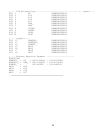
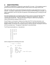
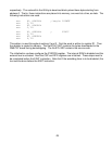
For example, the initialization code starting at address 0 begins with the two instructions
DISWDT
EINIT
whose machine instructions are (A5 5A A5 A5) and (B5 4A B5 B5),