


- -17
7 HEADERS AND JUMPERS
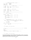
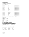
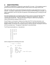
7.1 System and I / O Headers
The RMB-167 board has three headers, two of which are compatible with those of the RMB-166.
The two RMB-166 headers, the input output port header JP2 and the system header JP1, are
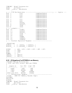
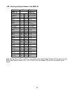
similar to the headers JP6 and JP7 of the RMB-167. In addition, the RMB-167 has JP8, the Extra
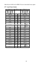
Input/Output header XIO. Ports 2, 3, and 5 are available on JP7. JP6 contains the address, data
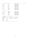
and control busses. JP8 contains the additional ports and signals of the SAB-C167
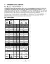
microcontroller. Individual signals of these jumpers are listed below. The tables reflect the
physical orientation of the headers and the enumeration of their individual posts. Pin 1 is
identified as the post with the square pad on the circuit board.
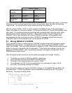
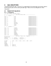
JP6 - System Header
Signal Pins Signal
RMB-
166
(JP1)
RMB-
167
(JP6)
RMB-
166
(JP1)
RMB-
167
(JP6)
Ground 1 2 VCC (+5V)
Ground 3 4 VCC (+5V)
D0 5 6 A0
D1 7 8 A1
D2 9 10 A2
D3 11 12 A3
D4 13 14 A4
D5 15 16 A5
D6 17 18 A6
D7 19 20 A7
D8 21 22 A8
D9 23 24 A9
D10 25 26 A10
D11 27 28 A11
D12 29 30 A12
D13 31 32 A13
D14 33 34 A14
D15 35 36 A15
RD# 37 38 A16
ALE 39 40 A17
RSTIN# 41 42 WR# WR# /
WRL#
RSTOUT# 43 44 BHE#
NMI# 45 46 not
used
A18
A22 not
used
47 48 not
used
A19
A21 not
used
49 50 not
used
A20