


Section 4 Verifying Operation
Rev. 3.00 Sep. 08, 2008 Page 15 of 18
REJ10J1396-0300
Section 4 Verifying Operation
1. Turn on the emulator according to the procedures described in the H8SX/1650 E6000H Emulator
User's Manual (HS1650EPH60HE).
2. Verify the user system interface cable connections by checking the pin states with the CHECK
command (emulator command). If an error is detected, recheck the soldered IC socket and the
location of pin 1.
3. The emulator connected to this user system interface cable supports three kinds of clock sources
as the MCU clock: an emulator internal clock, an external clock on the user system, and a crystal
oscillator to be mounted on the EV-chip board. For details, refer to the H8SX/1650 E6000H
Emulator User's Manual (HS1650EPH60HE).
⎯ To use the emulator internal clock
Select the clock in the emulator by using the CLOCK command (emulator command).
⎯ To use the external clock on the user system
Select the external clock with the CLOCK command (emulator command). Supply the
external clock from the user system to the emulator by inputting the external clock from the
EXTAL terminal on the cable head or connecting a crystal oscillator to the EXTAL and
XTAL terminals. For details, refer to the H8SX/1520 Group Hardware Manual.
⎯ To use the crystal oscillator mounted on the EV-chip board
Install a crystal oscillator into the crystal oscillator terminals on the EV-chip board.
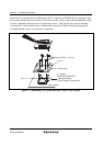
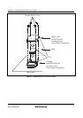
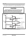
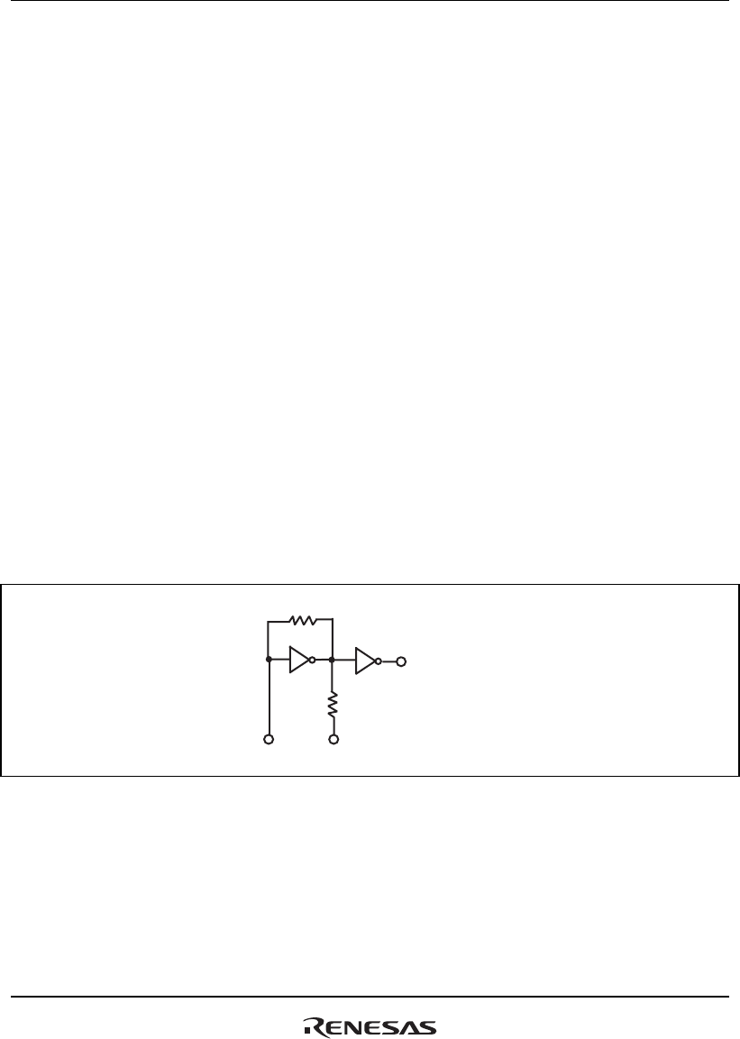
Figure 10 shows the oscillator circuit on the user system interface cable.
270 Ω
1 MΩ
HCU04
HCU04
To E6000H
emulator
EXTAL XTAL
Figure 10 Oscillator Circuit