


Section 5 Notice
Rev. 3.00 Sep. 08, 2008 Page 18 of 18
REJ10J1396-0300
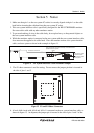
P4 short connector. For details on the differences between the target MCU and the emulator,
refer to the H8SX/1650 E6000H Emulator User's Manual (HS1650EPH60HE). For the ranges
of input voltages of AVcc0 and AVcc1, refer to the H8SX/1520 Group Hardware Manual.
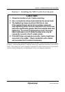
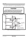
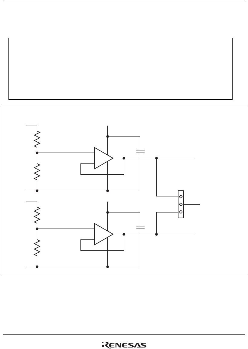
CAUTION
Insert the jumper pin in the P4 short connector so that
the higher voltage between AVcc0 and AVcc1 is selected.
Select either AVcc0 or AVcc1 when their potentials are
the same. Do not use the emulator without jumper pins.
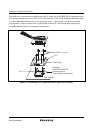
AVcc0
AVss
AVcc1
AVss
1.03 k
2 k
1.03 k
2 k
+
-
+
-
5 V
5 V
1
3P4
UVREF3
AVcc of MCU
of the emulator
station
UVREF1
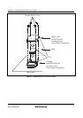
Settings of short connector:
Between pins 1 and 2: AVcc0
Between pins 2 and 3: AVcc1
User system interface Emulator station
Figure 13 Level-shift Circuit with AVcc0 and AVcc1