


Section 5 Notice
Rev. 3.00 Sep. 08, 2008 Page 17 of 18
REJ10J1396-0300
Section 5 Notice
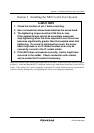
1. Make sure that pin 1 on the user system IC socket is correctly aligned with pin 1 on the cable
head before inserting the cable head into the user system IC socket.
2. This user system interface cable is specifically designed for the HS1527KEPH60H emulator.
Do not use this cable with any other emulator station.
3. To prevent breaking of wires in the cable body, do not place heavy or sharp metal objects on
the user system interface cable.
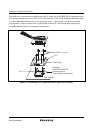
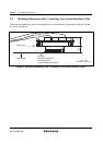
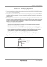
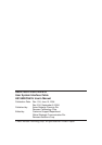
4. While the emulator station is connected to the user system with the user system interface cable,
force must not be applied to the cable head. Place the emulator station, user system interface
cable, and user system as shown in the example in figure 11.
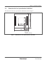
User system
Cable
Emulator's front-end unit
Place components so that the cable body and cable head are
parallel to the user system.
Cable head is parallel
to emulator station
Cable head is parallel
to user system
Figure 11 User System Interface Cable Location Example
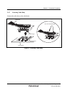
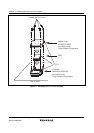
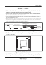
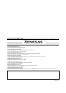
5. The P1 short connector is used for testing. Do not remove the jumper pin that is inserted in
the side of pins 1 and 2.
P1
31
P4
13
Figure 12 P1 and P4 Short Connectors
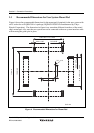
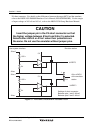
6. A level-shift circuit with AVcc0 and AVcc1 is mounted on the user system interface cable, as
shown in figure 13. At shipment, the jumper pin is inserted in the side of pins 1 and 2 of the