


( 18 / 38 )
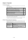
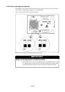
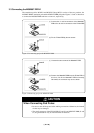
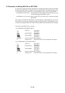
Figure 3.1 Positions of the switches and their factory-settings
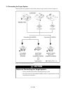
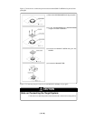
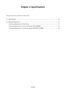
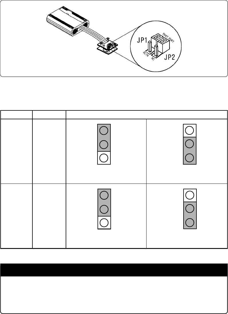
Table 3.1 Switch settings of the FLX64-PRB
Switch No. Switch settingFunction
Switches
P71/X
CIN
JP1
When using the port function (P71)
(Factory-setting)
When using the sub-clock
IMPORTANT
Note on Settings of JP1 and JP2:
• Change the switch setting of JP1 and JP2 at the same time as shown in Table 3.1.
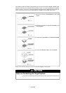
Chapter 3. Setting Up
With this product, it is necessary to set the following according to your target system.
• Switching ports (P70 and P71) and sub-clock
• Mounting the A-D conversion bypass capacitor
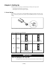
3.1 Switch Settings
It is necessary to set the switches of the FLX64-PRB for debugging according to the target system.
Figure 3.1 shows the positions of the switches of the FLX64-PRB, and Table 3.1 shows the switch
settings.
PORT
XCIN
PORT
XCIN
Switches
P70/NC
JP2
PORT
NC
PORT
NC
When using the port function (P70)
(Factory-setting)
When using the sub-clock