


( 32 / 38 )
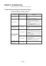
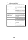
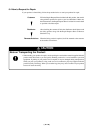
(3) Errors Occur When Starting Up the Emulator Debugger
(When the target system is not connected)
Table 5.3 Checkpoints of errors when starting up emulator debugger (target is not connected)
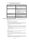
5.2 Operation Differs from That of Actual MCUs
Make note of the fact that the operation when using the emulation pod differs from that of actual
MCUs as follows.
(1) Initializing the internal resources of MCU at power-on
(2) Internal memories (ROM and RAM) capacities, etc.
With this emulator system, "INT" (emulation memory ON) is the default for mapping areas other
than the SFR area (addresses 000h - 3FFh). For this reason, the emulation memory can read and
write in areas other than the SFR, internal RAM and internal ROM.
(3) Oscillator circuit
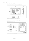
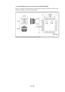
• Make note of the fact that in the oscillator circuit where a resonator is connected between the
XIN and XOUT pins, oscillation does not occur because a flexible cable, buffer IC and other devices
are used between the evaluation MCU and the target system. It is same for sub-clock oscillator
circuits (XCIN and XCOUT ).
•For note on when using the oscillator circuit on the target system, refer to "4.2 (2) Using target
system's oscillator" (page 21).
(4) XOUT pin
The XOUT pin is not assigned to the evaluation MCU used by this product. For this reason, the XOUT
pin of this product is open.
(5) DBC, single-step and BRK instruction interrupt vector table addresses
It is possible to download to DBC, single-step and BRK instruction interrupt vector table
addresses. However, because the emulator system uses these areas, data different from the
expected value is read out.
(6) A-D conversion
The characteristics of A-D converter differ from those of actual MCU because there are a flexible
cable, pitch converter and other devices between the evaluation MCU and the target system. Make
the final evaluation of the A-D converter with the actual MCU.
Error
Communication ERROR
Data is not sent to the target
Target system is not constructed properly
The version of M3T-PD30 and the firmware
on the target are not same
Target MCU is in "HOLD" state
Target clock is stopped
Checkpoint
Check all emulator debugger settings, interface cable
connections and switches on the rear of the PC4701
match.
See the user's manuals of the PC4701 and emulator
debugger.
(1) Download the proper firmware.
See the user's manual of the emulator debugger.
(2) Recheck the connection between the M30200T-RPD-
E and this product.
See "3.3 Connecting the M30200T-RPD-E" (page 20).
(3) Recheck the connection between the PC4701 and
the M30200T-RPD-E.
See the M30200T-RPD-E User's Manual.
Download the proper firmware.
See the user's manual of the emulator debugger.
The MCU is either in the stop mode or wait mode. Either
reset the MCU or cancel the mode with an interrupt.
See MCU specifications.
Check the switches of the FLX64-PRB are correctly set.
See "3.1 Switch Settings" (page 18).