


M30870T-EPB User’s Manual 2. Setup
REJ10J0482-0300 Rev.3.00 February 16, 2006
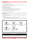
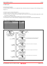
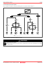
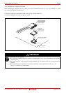
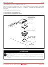
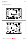
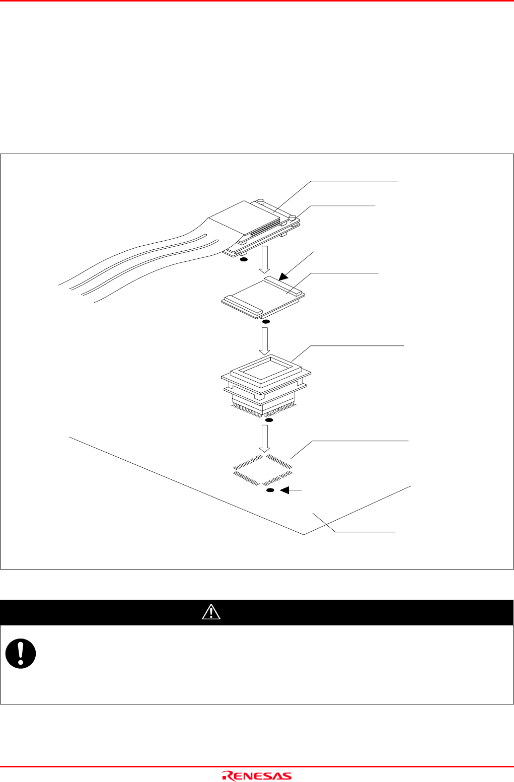
2.9.5 Connecting to a 100-pin 0.5-mm-pitch Foot Pattern (Part 1)
Figure 2.12 shows how to connect the emulation probe to a 100-pin 0.5-mm-pitch foot pattern on the user system with the
M3T-100LCC-QSD (not included), and here following is its procedure. For details on the M3T-100LCC-QSD, refer to its
user's manual.
(1) Attach the M3T-100LCC-QSD to the user system.
(2) Attach the M30800T-PTC to the M30870T-EPB.
(3) Attach the M30800T-PTC to the M3T-100LCC-QSD.
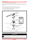
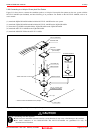
Figure 2.12 Connecting to a 100-pin 0.5-mm-pitch foot pattern (1/3)
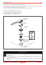
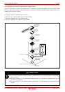
CAUTION
Notes on Connecting the User System:
Take care not to attach the converter board in a wrong direction. It may cause a fatal damage to the emulator
and user system.
The small connectors of the M30870T-EPB and M30800T-PTC are guaranteed for only 50 insertion/removal
iterations.
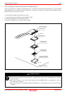
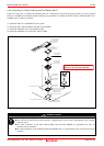
M3T-100LCC-QSD
(not included)
M3T-FLX160-EPB
M30870T-EPB
CN2 side
(2)
(3)
M30800T-PTC
(1)
100 -pin 0.5-mm -pitch
(100P6Q) foot pattern
No. 1 pin
User system
Page 34 of 104