


M30870T-EPB User’s Manual 4. Hardware Specifications
REJ10J0482-0300 Rev.3.00 February 16, 2006
IMPORTANT
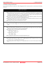
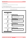
Notes on A/D Conversion:
When selecting the following MCU files in the Init dialog box of the emulator debugger to execute the A/D
conversion debug, note the following.
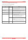
M32C PC7501 Emulator Debugger: m30870_ad.mcu
M3T-PD308F: m30870_ad_a.mcu
When setting the register below to use the analog input port selection function, you need to set the direction
register of port P15 for a pin that performs A/D conversion to "input".
And you need to set the function selection register of port P15 for a pin that performs A/D conversion to "I/O
port".
A/D0 control register 2 (address 394h)
b2, b1
1, 0 : AN00 to AN07
1, 1 : AN20 to AN27
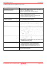
Also, when the P0 and P2 groups are selected for A/D input, port P15 cannot be used as an I/O port. When
setting the register above, port P15 cannot be used as an I/O port even if A/D conversion is halting.
For the switch SW5, refer to "2.10.1 Setting Switches of Emulation Probe" (page 38).
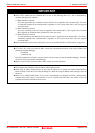
When setting the register below to use multi-port sweep mode, you need to set the direction register of port P15
for a pin that performs A/D conversion to "input".
And you need to set the function selection register of port P15 for a pin that performs A/D conversion to "I/O
port".
A/D0 control register 4 (address 392h)
b3, b2
1, 0 : AN0 to AN7, AN00 to AN07
1, 1 : AN0 to AN7, AN20 to AN27
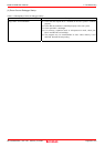
Also, when the P0 and P2 groups are used for multi-port sweep mode, port P15 cannot be used as an I/O port.
When setting the register above, port P15 cannot be used as an I/O port even if A/D conversion is halting.
Because a converter board and other devices are used between the evaluation MCU and the user system, the
A/D converter operates differently from an actual MCU. Make the final evaluation of the A/D converter using
an actual MCU.
Page 94 of 104