


M30880T-EPB User’s Manual 4. Hardware Specifications
REJ10J0497-0100Z Rev.1.00 January 16, 2005
Page 78 of 100
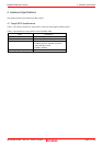
4.2 Differences between the Actual MCU and Emulator
Differences between the actual MCU and emulator are shown below. When debugging the MCU using this product, be careful
about the following precautions.
IMPORTANT
Note on Differences between the Actual MCU and Emulator:
Operations of the emulator system differ from those of actual MCUs as listed below.
(1) Reset condition
(2) Initial values of internal resource data of an MCU at power-on
(3) Interrupt stack pointer (ISP) after a reset is released
(4) Capacities of the internal memories (ROM and RAM)
The MCU whose RAM size is 18 KB (400h--4BFF) is mounted on this product. The internal flash memory
is automatically allocated to F000h--FFFFh and F80000h--FFFFFFh in the single-chip mode.
(5) Oscillator circuit
- Make note of the fact that in the oscillator circuit where a resonator is connected between pins X
IN
and
X
OUT
, oscillation does not occur because a converter board and other devices are used between the
evaluation MCU and the user system. It is same for a sub-clock oscillator (X
CIN
and X
COUT
).
- For notes on when using the oscillator circuit on the user system, refer to "(2) Using the Oscillator
Circuit on the User System" (page 46).
(6) A/D conversion
As a converter board and other devices are used between the evaluation MCU and the user system, some
characteristics are slightly different from those of an actual MCU.
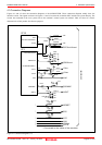
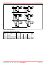
(7) Port P15
As one of I/O ports (P15) is connected to the user system through the analog switch circuit, electric
characteristics slightly differ from those of an actual MCU.
(8) When the SW4 is set to XOUT in stop mode, a clock is output from the XOUT pin.
Note on RESET* Input:
A low input to pin RESET* from the user system is accepted only when a user program is being executed (only
while the RUN status LED on the emulator's upper panel is lit).
Note on NMI* Input:
A low input to pin NMI* from the user system is accepted only when a user program is being executed (only
while the RUN status LED on the emulator's upper panel is lit).