


( 6 / 12 )
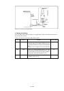
(3) Set the MCU type selection switch (SW1) of the M38000TL2-FPD as shown in Table 4.2.
Table 4.2 Settings of the SW1 of the M38000TL2-FPD
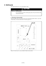
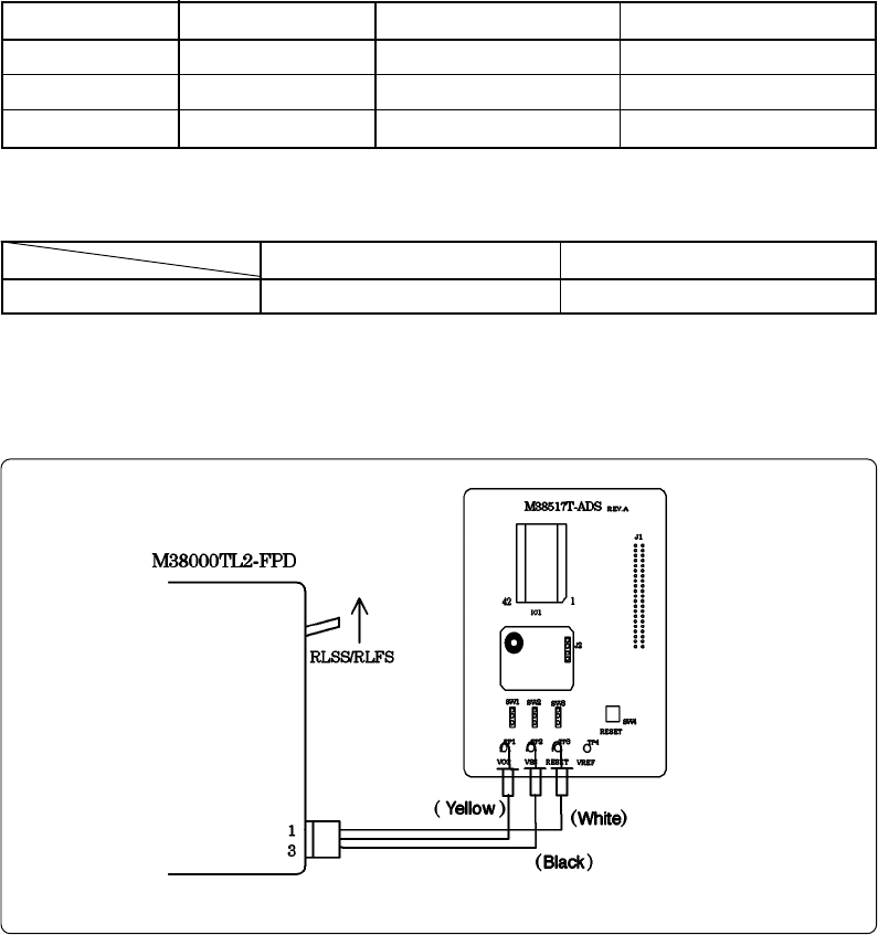
Figure 4.2 Connecting the M38507ARLSS
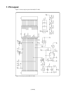
4.2 Connecting to the Emulation Pod
(1) Insert the connector on the tip of the emulation pod probe to the socket on the emulator MCU.
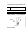
(2) Connect the cables of the M38000TL2-PSW2 as shown in Table 4.1 depending on the emulator
MCU you use.
Do not connect the Vcc cable (yellow) to pin Vcc (TP1).
Table 4.1 Connector cables of the M38000TL2-PSW and applicable signals
Cable color
White
Black
Yellow
Signal
RESET
Vss
Vcc
For M38507ARLSS
TP3
TP2
TP1
For M38517RSS
TP3
TP2
No connection
M38507ARLSS
RLSS/RLFS
M38517RSS
RSS/RFS
M38000TL2-FPD SW1
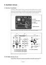
(4) Connect a power supply (not included) to pin Vcc (TP1) of the M38517T-ADS. And connect the
GND output of the power supply to pin Vss (TP2). Use the power supply whose rising time is 10
ms or less.