


( 8 / 12 )
5. Oscillator Circuit
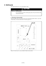
5.1 Oscillator Circuit Board
The M38517T-ADS has a built-in oscillator circuit board on which a 4.0MHz oscillator is mounted.
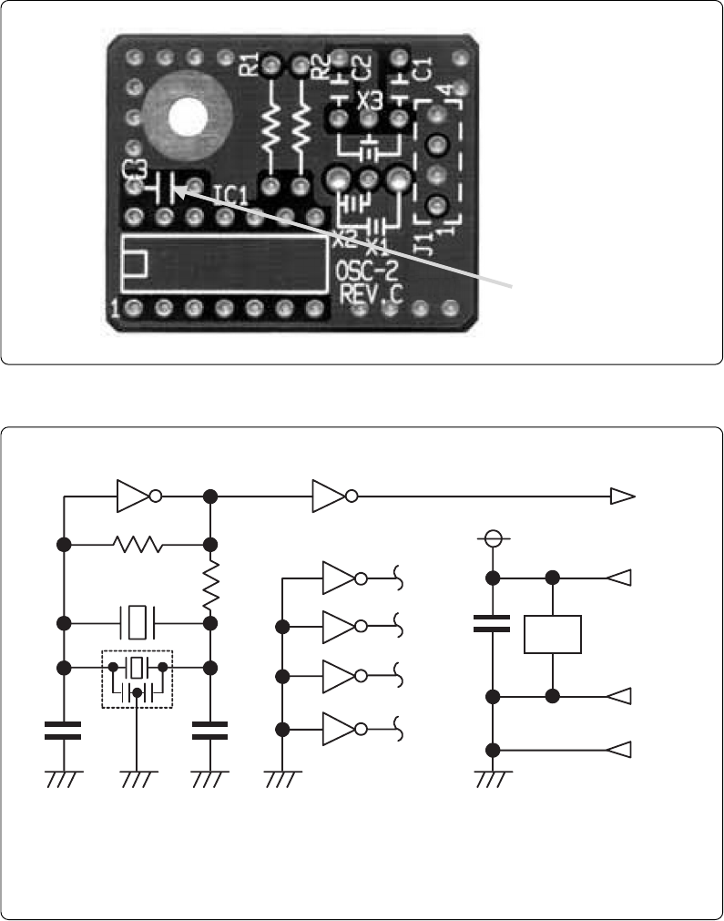
Figure 5.1 shows an external view of the OSC-2 oscillator circuit board (bare board) and where
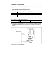
connector pins are located. Figure 5.2 shows the circuitry of the OSC-2 oscillator circuit board (bare
board). Use the number of oscillator circuits recommended by the oscillator manufacturer.
Figure 5.1 External view of the oscillator board (OSC-2) and connector pin assignment
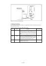
Figure 5.2 Circuit of the oscillator board (OSC-2)
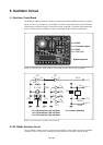
5.2 32.768kHz Oscillator Circuit
The 32.768kHz oscillator circuit is prepared on the M38517T-ADS. When using the 32.768kHz
oscillator circuit as a sub-clock, set the short-circuit connector of the SW1 to the XCIN side.
Bypass capacitor
J1-4: GND
J1-3: Oscillator output
J1-2: GND
J1-1: VCC (5 V)
* X1: 5.08-mm-pitch 2-pin oscillator IC1: Inverter (Unbuffer)
* X2: 2.54-mm-pitch 2-pin oscillator
* X3: 2.54-mm-pitch 3-pin oscillator
IC1
R1
C2
C1
X1 ,X2
CLK
Vcc
GND
R2
J1-3
1011 8
9
2
1
4
3
6
5
12
13
C3
IC1
J1-1
J1-2
J1-4
GND
IC
1
**
X3
*
IC1
14
7