


( 6 / 14 )
4. Setting Up
This chapter describes how to set up the M38C89T-ADF.
With this product, the debugging with an emulator MCU and M38C89MF-xxxFP/M38C89EFFP is
possible. Use the M38C89T-ADF mounting one of these MCUs.
To use an emulator MCU:
Read "4.1 Connecting to the Emulator" (this page)
To use the M38C89MF-xxxFP/M38C89EFFP:
Read "4.2 Mounting the M38C89MF-xxxFP/M38C89EFFP" (page 8)
CAUTION
Note on Setting Up:
• Always shut OFF power before connecting the M38C89T-ADF.
• Do not mount the IC1 and IC2 at the same time. Mount either of them only.
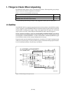
4.1 Connecting to the Emulator
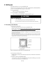
(1) Mounting the emulator MCU
Mount the emulator MCU in the IC2 socket on the M38C89T-ADF.
Raise the socket's clamp and insert the emulator MCU flush against the socket's left and bottom
sides, placing the "•" marking on the emulator MCU at the right bottom corner. Then, lower the
clamp to lock the emulator MCU in place.
If your emulator MCU does not have the "•" marking on it, use one pin (back of the MCU) for
positioning as shown below.
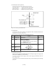
MCUs have 20 x 20 pins to the socket's 21 x 21 holes. Since there are more socket holes to MCU
pins, insert the MCU flush against the socket's left and bottom sides. The socket is taped to prevent
improper MCU mounting. Do not peel off the tape.
Figure 4.1 Mounting the emulator MCU on the M38C89T-ADF
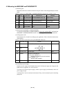
(2) Connecting the emulation probe
Insert the connector on the tip of the emulation pod probe to the J1 of this board. For the direction,
see Figure 4.2.
(3) Setting the emulation pod (M38000TL2-FPD)
As the applicable emulator MCU (M38C89RLFS) for this product is RLFS type, set the switch
on the side of the emulation pod to RLSS/RLFS side.