


( 8 / 14 )
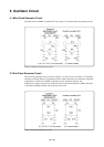
4.2 Mounting the M38C89MF-xxxFP/M38C89EFFP
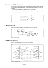
(1) Mounting parts
Mount the socket for IC1 and the oscillator circuit part. Table 4.2 lists the applicable parts for this
board.
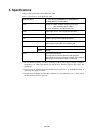
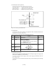
Table 4.2 Socket for the M38C89MF-xxxFP/M38C89EFFP and applicable oscillator circuit
(2) Mounting the M38C89MF-xxxFP/M38C89EFFP
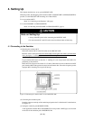
To mount the M38C89MF-xxxFP/M38C89EFFP, remove the emulator MCU and install the
M38C89MF-xxxFP/M38C89EFFP in the IC1 socket. Align pin No. 1 with the printed mark.
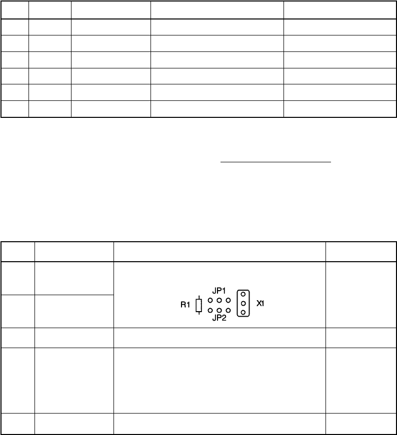
(3) Setting jumpers (JP)
Set the jumpers (J1 to J4 and J7) according to your applications. Table 4.3 describes the functions
of the jumpers.
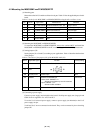
Table 4.3 Functions of the jumpers (JP) of the M38C89T-ADF (2/2)
Name
JP1
JP2
JP3
JP4
JP7
Applicable signal
XIN
XOUT
Vss (NC)-VLIN
OSCSEL
VccM-VccU
Function
R1 side: RC oscillation, X1 side: Oscillation by X1
Factory-setting
Open
Open
Short-circuit
Open
Remain Open.
Switches the OSCSEL pin
• Short-circuit: OSCSEL = "L"
Selects the oscillation by ceramic resonator
• Open: OSCSEL = "H"
Selects the RC oscillation
For short-circuit of VccM-VccU
(4) Connecting a power supply
Connect a power supply (not included) to the board's VccM power supply test (large) pin and
GND. Power is supplied to Vcc of IC1 and IC2.
To use the VccU universal power supply, connect a power supply (not included) to the VccU
power supply test pin.
VccM and VccU are not connected on the board. They can be connected by short-circuiting
jumper JP7.
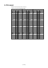
No.
1
2
3
4
5
6
Part No.
IC1
X1
XC1
C5, C6
R2
R3
Type name
IC51-1444-1354-18
CST4.00MGW040
SP-T2B 32.768 kHz
RPE132CH100J50
-
RD16S 6.8MΩJ
Manufacturer
Yamaichi Electronics Co., Ltd.
Murata Manufacturing Co., Ltd.
Seiko Instruments Inc.
Murata Manufacturing Co., Ltd.
-
KOA
Remarks
144-pin socket
Built-in capacitor type, 4 MHz
On-board type
10 pF
0 Ω, short-circuit
6.8 MΩ