


( 7 / 14 )
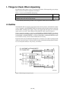
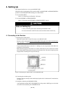
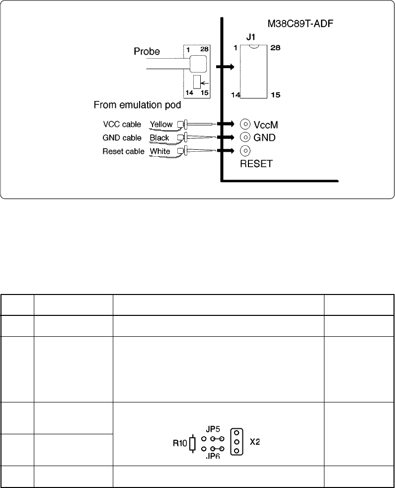
(4) Connecting the control signal lines
Connect the three lines of the emulation pod to the test pins.
VCC cable (yellow) ........... VccM (test pin with a yellow bead)
GND cable (black) ............. GND (test pin with a black bead)
Reset cable (white)............. RESET (test pin with a white bead)
Figure 4.2 Connecting the M38C89T-ADF
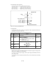
(5) Setting jumpers
Set the jumpers (JP3 to JP7) according to your application. Table 4.1 describes the functions of
the jumpers for the emulator MCU (IC2).
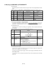
Table 4.1 Functions of the jumpers (JP) of the M38C89T-ADF (1/2)
(6) Connecting a power supply
Connect a power supply (not included) to the board's VccM power supply test (large) pin and
GND. Power is supplied to Vcc of IC1 and IC2.
To use the VccU universal power supply, connect a power supply (not included) to the VccU
power supply test pin.
VccM and VccU are not connected on the board. They can be connected by short-circuiting
jumper JP7.
Name
JP3
JP4
JP5
JP6
JP7
Applicable signal
Vss (NC)-VLIN
OSCSEL
XIN
XOUT
VccM-VccU
Function
Remain Open.
Switches the OSCSEL pin
• Short-circuit: OSCSEL = "L"
Selects the oscillation by ceramic resonator.
• Open: OSCSEL = "H"
Selects the RC oscillation.
R10 side: RC oscillation, X2 side: Oscillation by X2
Factory-setting
Open
Short-circuit
X2 side
Open
For short-circuit of VccM-VccU