


( 9 / 14 )
5. Oscillator Circuit
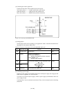
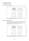
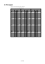
5.1 Main Clock Generator Circuit
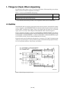
The main clock of 4.0 MHz is mounted (X2 only). Figure 5.1 shows the main clock generator circuit.
Figure 5.1 Main clock generator circuit
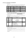
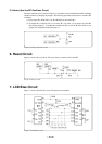
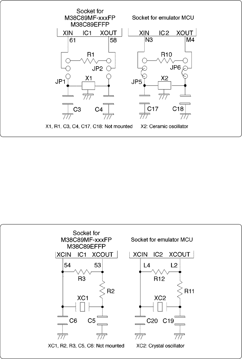
5.2 Sub Clock Generator Circuit
The sub clock generator circuit is shown in Figure 5.2. The sub clock oscillates at 32.768 kHz.
Capacitors C19 and C20 have a capacitance of 10 pF, while resistor R11 has a resistance of 0 Ω and
resistor R12 a resistance of 6.8 MΩ. Components are not mounted on the IC1 side.
If MCU power supply voltage is low, it will take time for sub clock oscillation to stabilize. Be aware
of this when changing from the main clock to the sub clock.
Figure 5.2 Sub clock generator circuit