


Operational Specifications
3.1.1 H-UDI Connector (J1,J2)
Rev.1.0 Feb 6, 2007 3-4
REJ10J0916-0100
3
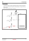
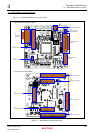
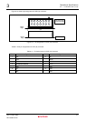
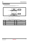
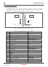
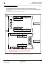
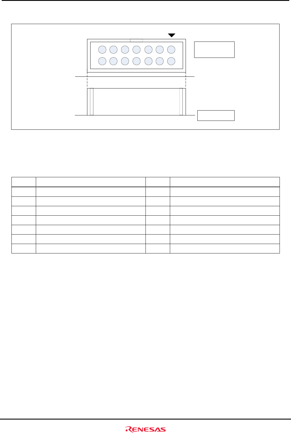
Figure3.1.3 shows a pin assignment of H-UDI (J2) connector.
7
14
6
13
5
12
4
11
3
10
2
9
1
8
Board
Edge
Top View of the
Component Side
Side View
J2
Board
Edge
Figure3.1.3 Pin Assignment of H-UDI (J2) Connector
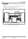
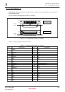
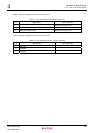
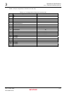
Table3.1.2 lists pin assignments of H-UDI (J2) connector.
Table3.1.2 Pin Assignments of H-UDI (J2) Connector
Pin Signal Name Pin Signal Name
1
TCK
8
NC
2
TRST
_________
9
(GND)
3
TDO
10
GND
4
ASEBRKAK
___________________
/ASEBRK
______________
11
UVCC
5
TMS
12
GND
6
TDI
13
GND
7
RES
_______
14
GND