


Operational Specifications
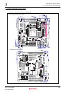
3.2 Outline of Switches and LEDs
Rev.1.0 Feb 6, 2007 3-17
REJ10J0916-0100
3
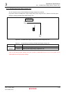
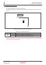
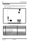
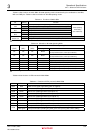
3.2 Outline of Switches and LEDs
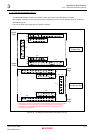
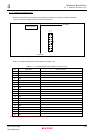
The M3A-HS86 includes switches and LEDs as its operational components.
Figure3.2.1 shows the M3A-HS86 operational component assignment.
<Top View of the Component Side >
User LED
6-8
SW1
Power Switch
SW4
DIP Switch
for System Setting
User
LED2-5
SW5
NMI
Switch
SW6
IRQ1
Switch
SW7
MRES
Switch
SW2
RESET
Switch
SW3
DIP Switch
for User
*
JP1
Power Supply
Select Jumper
JP2
FWE Pin
Select
Jumper
LED1
Power LED
LED9
LED for Interrupt
Confirmation
Note : * Not mounted
Figure3.2.1 M3A-H86 Operational Component Assignment