


Operational Specifications
3.2.3 Switch and LED Functions
Rev.1.0 Feb 6, 2007 3-20
REJ10J0916-0100
3
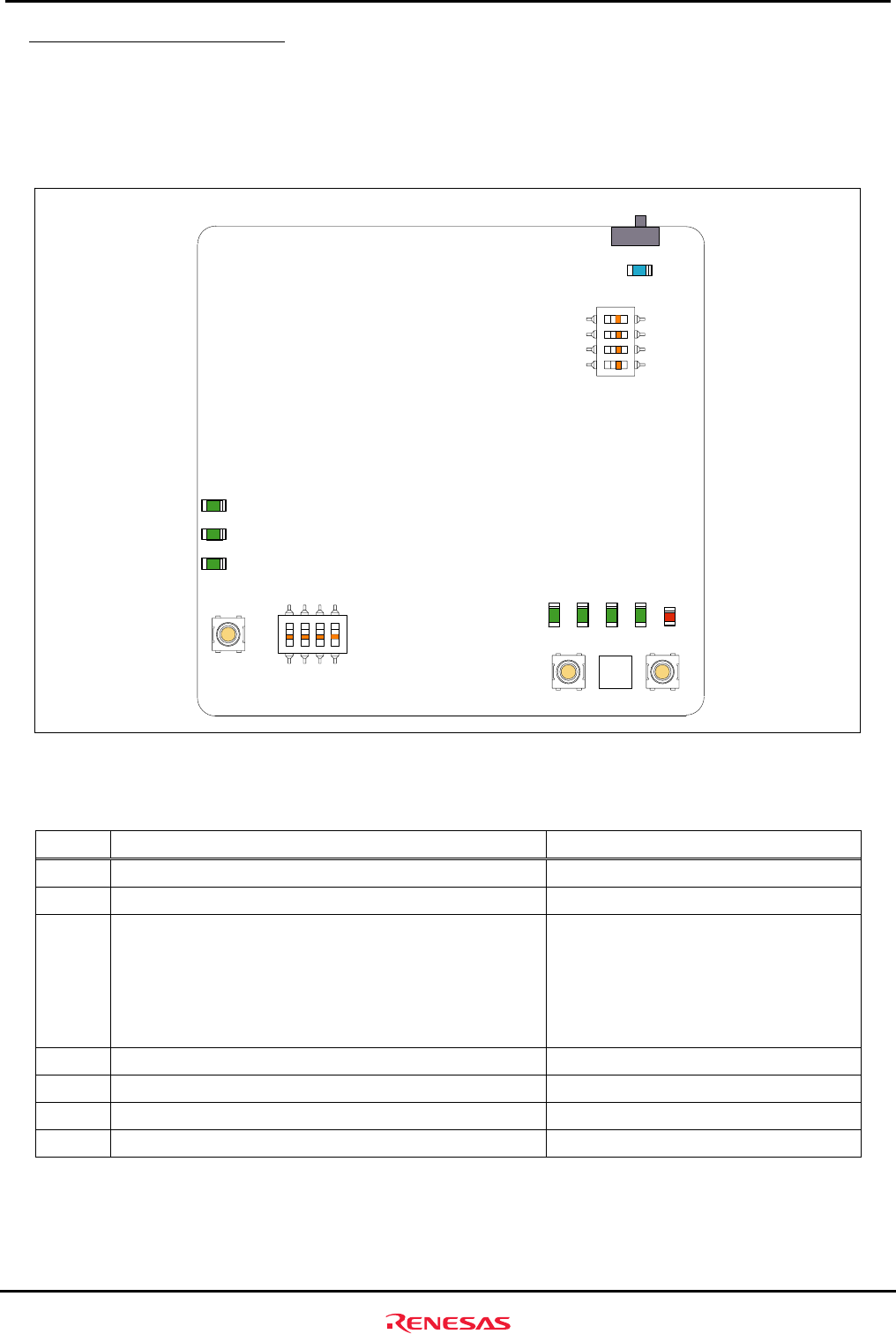
3.2.3 Switch and LED Functions
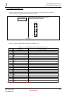
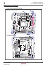
The M3A-HS86 includes six switches and nine LEDs. The MRES switch can be mounted as the option. However,
MRES
_____________
pin is multiplexed with ASEBRKAK
_____________________
/ASEBRK
________________
pin, so do not mount the switch MRES when H-UDI
connectors (J1, J2) are used. Figure3.2.4 shows the switch and LED pin layout on M3A-HS86 board. Table3.2.3
lists switches mounted on M3A-HS86.
<Top View of the Component Side >
SW1
LED1
ON OFF
FLWP
MD0
MD1
FWE
SW4
LED6
PE16
PE17
PE18
LED7
LED8
RESET
SW2
1234
ON
SW3
PB6
PB7
PB8
PB9
NMI
MRES IRQ1
SW5 SW7 SW6
PE1
PE2
PE7
PE14
LED9
ON
LED2
LED3
LED4
LED5
Figure3.2.4 Switch and LED Pin Assignment on M3A-HS86 Board
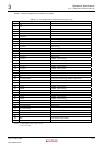
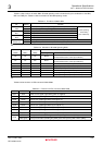
Table3.2.3 Switches Mounted on M3A-HS86
No. Function Remarks
SW1 System power on/off switch -
SW2 System reset input switch See section 2.8 for details.
SW3 DIP switch open to the user (4-pole)
SW3-1 OFF : PB6=H, ON : PB6=L
SW3-2 OFF : PB7=H, ON : PB7=L
SW3-3 OFF : PB8=H, ON : PB8=L
SW3-4 OFF : PB9=H, ON : PB9=L
PB6, PB7, PB8 and PB9 are pulled up.
See section 2.5 on chapter 2 for details.
SW4 System setup DIP switch (4-pole) See
Table3.2.4
for the functions
SW5 NMI input switch See section 2.9 of chapter 2 for details.
SW6 IRQ1 input switch See section 2.9 of chapter 2 for details.
SW7 MRES
*
input switch Not mounted.
*: By MRES (manual reset), each register of the on-chip peripheral module is not initialized though an internal state of
CPU is initialized.