


M61323SP/FP
REJ03F0201-0201 Rev.2.01 Mar 31, 2008
Page 10 of 19
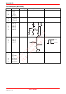
<Sync-Separation>
Sync Input Minimum Voltage
Gradually decreasing the amplitude of SG7 in pin 22, measure the amplitude of SG7 when the Sync-Sep output signal
turn off. The value is as SYrv.
Sync Output High Level Voltage/Sync Output Low Level Voltage
Input SG7 to pin 22, read the output high level and low voltage of TP21. The value is as SYVH, SYVL.
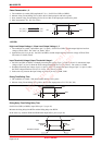
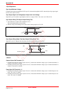
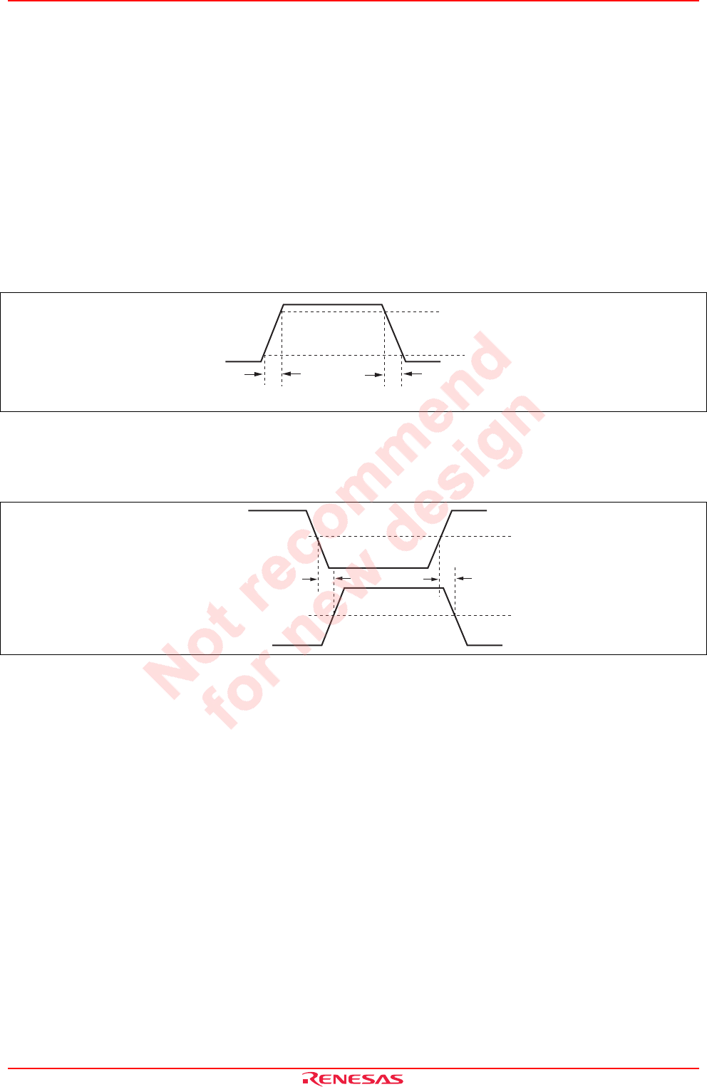
Sync Output Rising Time/Sync Output Falling Time
1. The conditions is as table. (SG7 amplitude 0.3 V
P-P
)
This measurement shall use active probe.
2. Measure rising Tri and falling Tfi for 10% to 90% of the input pulse as STr, STf.
100%
0%
10%
90%
STr STf
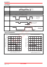
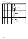
Sync Output Rising Delay Time/Sync Output Falling Delay Time
Input SG7 to pin 22. Measure the rising delay time SDr and the falling delay time SDf.
50%
50%
SG7
Waveform output
SDr SDf
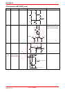
<Others>
Channel Select SW Threshold 1, 2
1. Gradually increasing the voltage of pin 13 from 0 V, measure the maximum voltage of pin 13 when the channel 1 is
selected. The value is as Vthch1.
2. Gradually decreasing the voltage of pin 13 from 5 V, measure the minimum voltage of pin 13 when the channel 2 is
selected. The value is as Vthch2.
Power Save SW Threshold 1, 2
1. Gradually increasing the voltage of pin 11 from 0 V, measure the maximum voltage of pin 11 when the power save
mode. The value is as VthPL.
2. Gradually decreasing the voltage of pin 13 from 5 V, measure the minimum voltage of pin 11 when the power save
mode. The value is as VthPH.