


RL78/G1C Group USB Charger Solution Kit R0K578G1CD010BR
R01AN1911EJ0101_RL78G1C Rev.1.01 Page 10 of 23
Apr 10, 2014
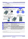
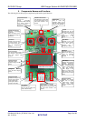
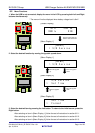
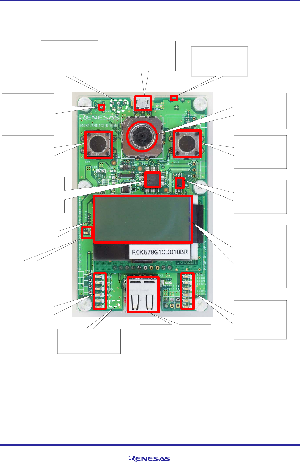
5. Components Names and Functions
The following shows the top layer component layout and key parts functions.
USB Micro
-
B Connector
USB interface to connect with
PC and other devices via the
USB cable included in this
product
.
HOLD Switch
Used to avoid miss
operations. When set to
right side, the board will not
react to any key operation.
Reset Button
(backside of PCB)
Press to clear all settings and
reset to default setting.
USB Standard
-A Connector
USB interface to connect with
Smartphone and other devices via
the USB cable included in this
product.
Temperature Sensor
(backside of PCB
)
Senses surrounding
temperature.
When warmed
by a hand, it senses a
change in temperature
.
RL78/G1C Microcomputer
[R5F10JGCAFB]
This microcontroller controls all
the functions in this product,
and also embeds USB
functions.
Charge Level LED
Indicates the charge level
with six orange-colored
LEDs. It blinks faster
when higher current is
charged in the battery.
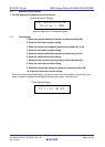
Left Button
Operate as the left click
of mouse functions.
It is
also used as Enter (
OK
)
key in configuration
settings.
Ambient Light Sensor
Measures surrounding
iluminance
.
When covered by a hand,
it displays the changes of
illuminance
.
Right Button
Operates as the right
click of mouse functions.
It is also used as
“Cancel” key in
configuration settings.
Supply Level LED
Indicates the supplying
level with six green-
colored LEDs. It blinks
faster when higher
current is supplied to the
module.
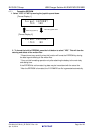
LCD Display
Displays various statuses
including temperature,
illuminance, battery level
,
time, charging/supplying
power.
It comes with a
white LED backlight.
When display is off,
device is in sleep mode.
Press either right or left
button to return to normal
mode
.
Joystick
Operating this part will
move the cursor. Use this
to select target items
when setting
configurations in the
menu.
EEPROM
[R1EX25512ATA001]
Stores sensor data and is
used as temporary
memory for the USB
interface.
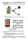
Charge Control IC
(back side of PCB)
Controls charging of Ni-
MH
battery.
Charge LED
Turns ON when charging
battery
.