


SH7145F
Asynchronous Serial Data Transmission/Reception
REJ06B0357-0100O/Rev.1.00 March 2004 Page 6 of 17
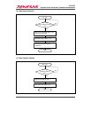
3. Operation
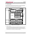
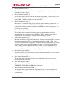
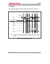
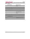
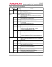
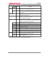
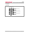
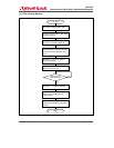
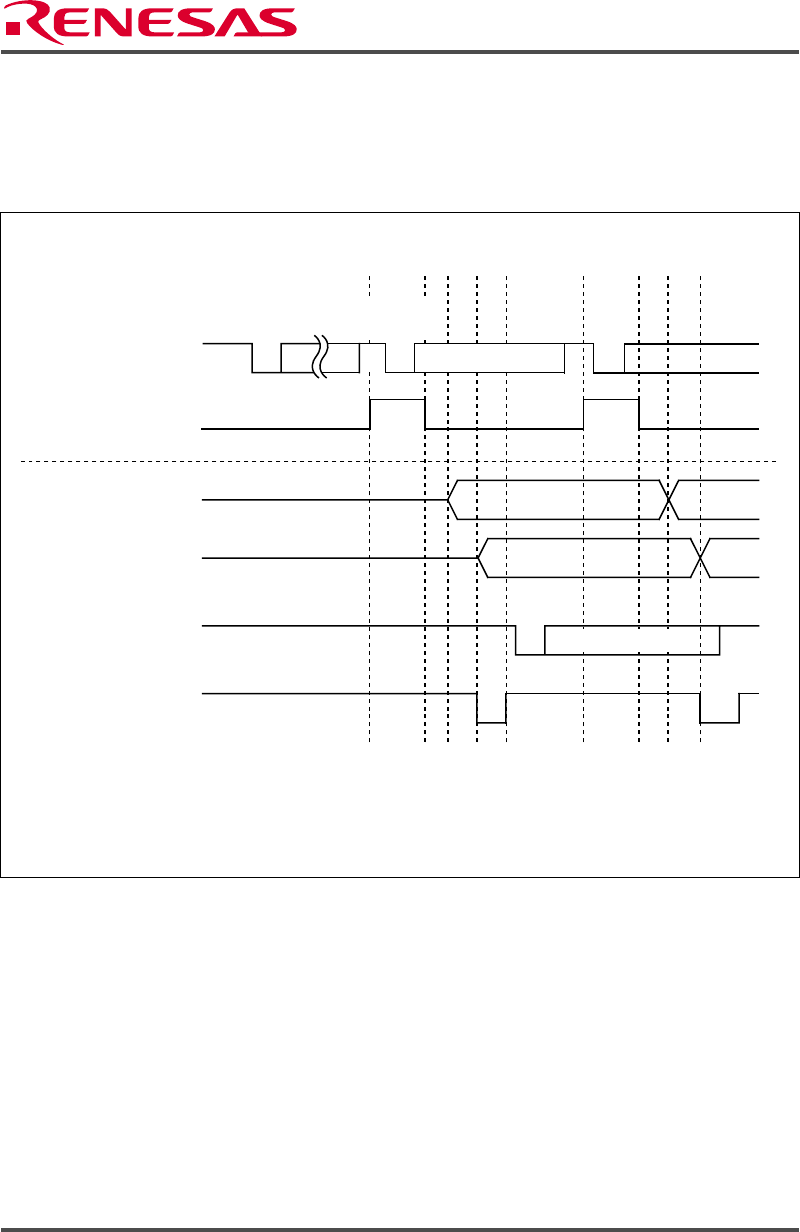
Figure 3 shows the operation of asynchronous mode data transmission in the task example. To
help explain figure 3, table 3 lists the software and hardware processing that is performed.
0
0
(1)
(2)
(3)
(4)
(5)
(6)
(7) (8)
(9)
(10)
(11)
(12)(13)
(14)
(15)
Data bits D0 to D7
Data bits D0 to D7
1
0
TxD1
(pin)
TDR_1
(register)
TSR_1
(register)
TXD1
(pin)
TDRE
(SSR_1 bit)
RDRF
(SSR_1 bit)
Receive operation
Notes: 1. The start bit, transmit data, parity bit, and stop bit are output, in that order, from the TxD1 pin.
2. To perform continuous reception, read data transferred to RDR until reception of next data is
complete.
Transmit operation
Start
bit
Start
bit
Start
bit
Stop
bit
Data
bits
Figure 3 Data Transmission Operation