


INSTALLATION
8
ULTRAVIEW PRO INSTALLATION AND OPERATIONS MANUAL
Organizing the system
It is recommended that before any UltraView Pro configuration or
cable connections be made, plan how the system will be laid out,
the placement of the CPUs and the placement of the UltraView Pro.
Take into consideration the cable lengths needed to connect to the
KVM station and each CPU. Identify which CPU will be connected to
computer 1’s DB25 connector, computer 2, and so on.
The default computer names that the UltraView Pro uses to identify
the computer are computer 1, computer 2, and so on. These names
can be changed using the on-screen “Configure computer” menu.
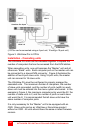
Installation – single unit
This section explains how to connect and initially configure the
UltraView Pro. If you are cascading two or more UltraView Pro units
together, please refer to the Cascade installation section.
NOTE: Some installation procedures and menu selections may not
be available on the PC model.
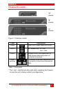
Step 1. Connecting the keyboard, video monitor, and mouse
Connect the KVM stations keyboard, video monitor and mouse
cables to the corresponding connectors of the appropriate KVM
cable as shown in Figure 3. The KVM cable should have the correct
connector types for the equipment used. Connect the DB25M
connector into the connector labeled “Monitor/Keyboard/Mouse” on
the UltraView Pro rear panel.
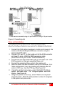
Step 2. Apply power to UltraView Pro
For the “M” chassis, connect the power transformer to a 110/220-
volt source and to the DIN 5F power adapter connector on the rear
panel. Press the ON/OFF button in the front panel once to turn on
the unit.
For the “B” and “C” chassis, connect a power cord to 110/220-volt
source and to the IEC320 connector on the rear panel. Press the
rocker switch to the ON position.