


ULTRAVIEW PRO INSTALLATION AND OPERATIONS MANUAL
9
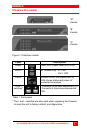
The green POWER LED will turn on and the power-on diagnostic
message will display on the KVM monitor. If the KVM monitor is
slow to acquire sync, the power-on diagnostic may not be seen.
Computer 1 is automatically connected on power-up. On the front
panel, the SELECT 1 LED will light and computer 1’s label will
display in the lower left corner of the KVM monitor for 5 seconds,
then disappear.
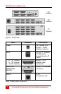
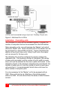
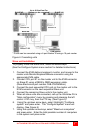
Step 3. Connecting the computers
(See Figure 3)
Connect each computer to the UltraView Pro using the appropriate
CPU cable. Connect the keyboard, video monitor, and mouse
connectors of the CPU cable to the corresponding keyboard, video
monitor, and mouse ports on the CPU.
Connect the DB25M end of the CPU cable to the DB25F CPU
connectors on the rear panel of the UltraView Pro. For ease of
installation and configuration, it is recommended that the CPUs be
off at this time. When a CPU is booted, the UltraView Pro can
automatically determine the keyboard and mouse types of the
connected CPU. If the CPUs power needs to be kept on, the
UltraView Pro should be pre-configured before the CPUs are
connected. (See the configuration menu section)
The UltraView Pro can be pre-configured before any computers are
connected. This allows for connecting the computers to the switch
while they are powered on and not disrupting service on critical
computers. If you need to connect computers while power is still
applied to them, configure the switches keyboard and mouse type
for each computer first using the configure computer menu, then
connect the CPU to the UltraView Pro using the appropriate CPU
cable. This procedure should only be performed if the computers
being connected with power on can hot switch the keyboard and
mouse without locking up the system.